Physics for Scientists and Engineers: A Strategic Approach with Modern Physics (4th Edition)
4th Edition
ISBN: 9780133942651
Author: Randall D. Knight (Professor Emeritus)
Publisher: PEARSON
expand_more
expand_more
format_list_bulleted
Videos
Textbook Question
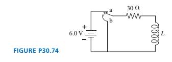
Chapter 30, Problem 74EAP
The inductor in FIGURE P30.74 is a - cm-long, -
 cm- diameter solenoid wrapped with
  turns. What is the current in the circuit
  after the switch is moved from a to b?
Expert Solution & Answer
Want to see the full answer?
Check out a sample textbook solution
Students have asked these similar questions
Please view both photos, and answer the question correctly please. Thank you!!
A thrown brick hits a window, but doesn't
break it. Instead it reverses direction and
ends down on the ground below the
window. Since the brick didn't break the
glass, we know:
О
The force of the brick on the glass >
the force of the glass on the brick.
О
The force of the brick on the glass
the force of the glass on the brick.
=
О
The force of the brick on the glass <
the force of the glass on the brick.
О
The brick didn't slow down as it broke
the glass.
Alexandra (wearing rubber boots for
traction) is attempting to drag her 32.6-kg
Golden Retriever across the smooth ice by
applying a horizontal force. What force
must she apply to move the dog with a
constant speed of 0.950 m/s?
☐ 31.0 lb.
☐ 319 kg.
○ Zero.
32.6 kg.
Chapter 30 Solutions
Physics for Scientists and Engineers: A Strategic Approach with Modern Physics (4th Edition)
Ch. 30 - Prob. 1CQCh. 30 - You want to insert a loop of copper wire between...Ch. 30 - A vertical, rectangular loop of copper wire is...Ch. 30 - Does the loop of wire in FIGURE Q30.4 have a...Ch. 30 - s5. The two loops of wire in FIGURE Q30.5 are...Ch. 30 - FIGURE Q30.6 shows a bar magnet being pushed...Ch. 30 - A bar magnet is pushed toward a loop of wire as...Ch. 30 - FIGURE Q30.8 shows a bar magnet. a coil of wire,...Ch. 30 - Prob. 9CQCh. 30 - An inductor with a 2.0 A current stores energy. At...
Ch. 30 - Prob. 11CQCh. 30 - Prob. 12CQCh. 30 - Rank in order, from largest to smallest, the three...Ch. 30 - For the circuit of FIGURE Q30.14: a. What is the...Ch. 30 - The earth’s magnetic field strength is 5.0105T ....Ch. 30 - A potential difference of 0.050 V is developed...Ch. 30 - A 10 -cm-long wire is pulled along a U-shaped...Ch. 30 - What is the magnetic flux through the loop shown...Ch. 30 - FIGURE EX30.5 shows a 10cm10cm square bent at a 90...Ch. 30 - Prob. 6EAPCh. 30 - Prob. 7EAPCh. 30 - FIGURE EX30.8 shows a 2.0 -cm-diameter solenoid...Ch. 30 - Prob. 9EAPCh. 30 - 10. A solenoid is wound as shown in FIGURE...Ch. 30 - 11. The metal equilateral triangle in FIGURE...Ch. 30 - The current in the solenoid of FIGURE EX3O.12 is...Ch. 30 - The loop in FIGURE EX30.13 is being pushed into...Ch. 30 - FIGURE EX30.14 shows a 10-cm-diameter loop in...Ch. 30 - Prob. 15EAPCh. 30 - 16. A -turn coil of wire cm in diameter is in a...Ch. 30 - A 5.0 -cm-diameter coil has 20 turns and a...Ch. 30 - FIGURE EX30.18 shows the current as a function of...Ch. 30 - The magnetic field in FIGURE EX30.19 is decreasing...Ch. 30 - The magnetic field inside a -cm-diameter solenoid...Ch. 30 - Scientists studying an anomalous magnetic field...Ch. 30 - Prob. 22EAPCh. 30 - Prob. 23EAPCh. 30 - Prob. 24EAPCh. 30 - Prob. 25EAPCh. 30 - Prob. 26EAPCh. 30 - How much energy is stored in a -cm-diameter,...Ch. 30 - MRI (magnetic resonance imaging) is a medical...Ch. 30 - Prob. 29EAPCh. 30 - Prob. 30EAPCh. 30 - Prob. 31EAPCh. 30 - Prob. 32EAPCh. 30 - Prob. 33EAPCh. 30 - Prob. 34EAPCh. 30 - At t=0 s, the current in the circuit in FIGURE...Ch. 30 - The switch in FIGURE EX3O.36 has been open for a...Ch. 30 - Prob. 37EAPCh. 30 - Prob. 38EAPCh. 30 - Prob. 39EAPCh. 30 - Prob. 40EAPCh. 30 - A 10cm10cm square loop lies in the xy-plane. The...Ch. 30 - A spherical balloon with a volume of L is in a mT...Ch. 30 - Prob. 43EAPCh. 30 - Prob. 44EAPCh. 30 - Prob. 45EAPCh. 30 - FIGURE P30.46 shows a 4.0-cm-diameter loop with...Ch. 30 - Prob. 47EAPCh. 30 - Prob. 48EAPCh. 30 - Prob. 49EAPCh. 30 - Prob. 50EAPCh. 30 - Prob. 51EAPCh. 30 - Prob. 52EAPCh. 30 - Prob. 53EAPCh. 30 - Prob. 54EAPCh. 30 - Prob. 55EAPCh. 30 - Your camping buddy has an idea for a light to go...Ch. 30 - 57. The -wide, zero-resistance slide wire shown...Ch. 30 - ]58. You’ve decided to make the magnetic...Ch. 30 - FIGURE P30.59 shows a U-shaped conducting rail...Ch. 30 - Prob. 60EAPCh. 30 - Prob. 61EAPCh. 30 - Prob. 62EAPCh. 30 - Equation 30.26 is an expression for the induced...Ch. 30 - Prob. 64EAPCh. 30 - One possible concern with MRI (see Exercise 28) is...Ch. 30 - FIGURE P30.66 shows the current through a 10mH...Ch. 30 - Prob. 67EAPCh. 30 - Prob. 68EAPCh. 30 - Prob. 69EAPCh. 30 - Prob. 70EAPCh. 30 - An LC circuit is built with a inductor and an...Ch. 30 - Prob. 72EAPCh. 30 - For your final exam in electronics, you’re asked...Ch. 30 - The inductor in FIGURE P30.74 is a -cm-long, -cm-...Ch. 30 - The capacitor in FIGURE P30.75 is initially...Ch. 30 - The switch in FIGURE P30.76 has been open for a...Ch. 30 - 77. The switch in FIGURE P30.77 has been open for...Ch. 30 - Prob. 78EAPCh. 30 - Prob. 79EAPCh. 30 - Prob. 80EAPCh. 30 - In recent years it has been possible to buy a 1.0F...Ch. 30 - Prob. 82EAPCh. 30 - Prob. 83EAPCh. 30 - Prob. 84EAPCh. 30 - A 2.0 -cm-diameter solenoid is wrapped with 1000...Ch. 30 - High-frequency signals are often transmitted along...
Knowledge Booster


Learn more about
Need a deep-dive on the concept behind this application? Look no further. Learn more about this topic, physics and related others by exploring similar questions and additional content below.Similar questions
- The figure shows a graph of the acceleration of an object as a function of the net force acting on it. The mass of this object, in grams, is closest to 11 a(m/s²) 8.0+ 6.0- 4.0- 2.0- 0+ F(N) 0.00 0.50 1.00 ☐ 130 ○ 8000 ☐ 89arrow_forwardValues that are within standard deviations represent measurements that are considered to be near the true value. Review the data from the lab and determine whether your data is within standard deviations. Report, using numerical values, whether your data for each angle is within standard deviations. An acceptable margin of error typically falls between 4% and 8% at the 95% confidence level. Review your data for each angle to determine whether the margin of error is within an acceptable range. Report with numerical values, whether your data for each angle is within an acceptable margin of error. Can you help explain what my data means in terms of the standard deviation and the ME? Thanks!arrow_forwardA sinusoidal wave is propagating along a stretched string that lies along the x-axis. The displacement of the string as a function of time is graphed in (Figure 1) for particles at x = 0 and at x = 0.0900 m. You are told that the two points x = 0 and x = 0.0900 m are within one wavelength of each other. If the wave is moving in the +x-direction, determine the wavelength. If instead the wave is moving in the -x-direction, determine the wavelength. Please show all stepsarrow_forward
- You are designing a two-string instrument with metal strings 35.0 cm long, as shown in (Figure 1). Both strings are under the same tension. String S1 has a mass of 8.30 g and produces the note middle C (frequency 262 Hz ) in its fundamental mode. What should be the tension in the string? What should be the mass of string S2 so that it will produce A-sharp (frequency 466 Hz ) as its fundamental? To extend the range of your instrument, you include a fret located just under the strings but not normally touching them. How far from the upper end should you put this fret so that when you press S1 tightly against it, this string will produce C-sharp (frequency 277 Hz ) in its fundamental? That is, what is x in the figure? If you press S2 against the fret, what frequency of sound will it produce in its fundamental?arrow_forwardPlease solve and answer the problem correctly please. Thank you!!arrow_forwardPlease help explain this. The experiment without the sandpaper had a 5% experimental error, with sandpaper it is 9.4%. Would the explaination be similar to the experiment without sandpaper? Thanks!arrow_forward
- A sinusoidal wave with wavelength 0.400 m travels along a string. The maximum transverse speed of a point on the string is 3.00 m/s and the maximum transverse acceleration is 8.10×10⁴m/s2. What is the propagation speed v of the wave? What is the amplitude A of the wave?arrow_forwardPlease help show how to find the standard deviation and margin of error. Please explain what they mean. Thanks!arrow_forwardPlease solve and answer the problem correctly please. Thank you!!arrow_forward
- Please solve and answer the question correctly please. Thank you!!arrow_forwardShould the results of your experimental Coefficient of Static Friction for the Wooden Block for the wooden block (Data Table 1) and the wooden block with the added mass (Data Table 2) be similar? Explain why or why not. Determine whether the results of the experiment are within a reasonable experimental error (< 10%) by calculating the % difference. Please help with showing how to calculate and with explaination, I'm not sure. Thanks!arrow_forwardNo chatgpt pls will upvote Alreadyarrow_forward
arrow_back_ios
SEE MORE QUESTIONS
arrow_forward_ios
Recommended textbooks for you
 Physics for Scientists and Engineers: Foundations...PhysicsISBN:9781133939146Author:Katz, Debora M.Publisher:Cengage Learning
 Principles of Physics: A Calculus-Based TextPhysicsISBN:9781133104261Author:Raymond A. Serway, John W. JewettPublisher:Cengage Learning
 Physics for Scientists and EngineersPhysicsISBN:9781337553278Author:Raymond A. Serway, John W. JewettPublisher:Cengage Learning
 Physics for Scientists and Engineers with Modern ...PhysicsISBN:9781337553292Author:Raymond A. Serway, John W. JewettPublisher:Cengage Learning
 College PhysicsPhysicsISBN:9781305952300Author:Raymond A. Serway, Chris VuillePublisher:Cengage Learning
Physics for Scientists and Engineers: Foundations...
Physics
ISBN:9781133939146
Author:Katz, Debora M.
Publisher:Cengage Learning
Principles of Physics: A Calculus-Based Text
Physics
ISBN:9781133104261
Author:Raymond A. Serway, John W. Jewett
Publisher:Cengage Learning
Physics for Scientists and Engineers
Physics
ISBN:9781337553278
Author:Raymond A. Serway, John W. Jewett
Publisher:Cengage Learning
Physics for Scientists and Engineers with Modern ...
Physics
ISBN:9781337553292
Author:Raymond A. Serway, John W. Jewett
Publisher:Cengage Learning
College Physics
Physics
ISBN:9781305952300
Author:Raymond A. Serway, Chris Vuille
Publisher:Cengage Learning
What is Electromagnetic Induction? | Faraday's Laws and Lenz Law | iKen | iKen Edu | iKen App; Author: Iken Edu;https://www.youtube.com/watch?v=3HyORmBip-w;License: Standard YouTube License, CC-BY