Physics for Scientists and Engineers: A Strategic Approach with Modern Physics (4th Edition)
4th Edition
ISBN: 9780133942651
Author: Randall D. Knight (Professor Emeritus)
Publisher: PEARSON
expand_more
expand_more
format_list_bulleted
Videos
Textbook Question
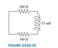
Chapter 30, Problem 35EAP
At
Expert Solution & Answer
Want to see the full answer?
Check out a sample textbook solution
Students have asked these similar questions
Please don't use Chatgpt will upvote and give handwritten solution
Please don't use Chatgpt will upvote and give handwritten solution
No chatgpt pls
Chapter 30 Solutions
Physics for Scientists and Engineers: A Strategic Approach with Modern Physics (4th Edition)
Ch. 30 - Prob. 1CQCh. 30 - You want to insert a loop of copper wire between...Ch. 30 - A vertical, rectangular loop of copper wire is...Ch. 30 - Does the loop of wire in FIGURE Q30.4 have a...Ch. 30 - s5. The two loops of wire in FIGURE Q30.5 are...Ch. 30 - FIGURE Q30.6 shows a bar magnet being pushed...Ch. 30 - A bar magnet is pushed toward a loop of wire as...Ch. 30 - FIGURE Q30.8 shows a bar magnet. a coil of wire,...Ch. 30 - Prob. 9CQCh. 30 - An inductor with a 2.0 A current stores energy. At...
Ch. 30 - Prob. 11CQCh. 30 - Prob. 12CQCh. 30 - Rank in order, from largest to smallest, the three...Ch. 30 - For the circuit of FIGURE Q30.14: a. What is the...Ch. 30 - The earth’s magnetic field strength is 5.0105T ....Ch. 30 - A potential difference of 0.050 V is developed...Ch. 30 - A 10 -cm-long wire is pulled along a U-shaped...Ch. 30 - What is the magnetic flux through the loop shown...Ch. 30 - FIGURE EX30.5 shows a 10cm10cm square bent at a 90...Ch. 30 - Prob. 6EAPCh. 30 - Prob. 7EAPCh. 30 - FIGURE EX30.8 shows a 2.0 -cm-diameter solenoid...Ch. 30 - Prob. 9EAPCh. 30 - 10. A solenoid is wound as shown in FIGURE...Ch. 30 - 11. The metal equilateral triangle in FIGURE...Ch. 30 - The current in the solenoid of FIGURE EX3O.12 is...Ch. 30 - The loop in FIGURE EX30.13 is being pushed into...Ch. 30 - FIGURE EX30.14 shows a 10-cm-diameter loop in...Ch. 30 - Prob. 15EAPCh. 30 - 16. A -turn coil of wire cm in diameter is in a...Ch. 30 - A 5.0 -cm-diameter coil has 20 turns and a...Ch. 30 - FIGURE EX30.18 shows the current as a function of...Ch. 30 - The magnetic field in FIGURE EX30.19 is decreasing...Ch. 30 - The magnetic field inside a -cm-diameter solenoid...Ch. 30 - Scientists studying an anomalous magnetic field...Ch. 30 - Prob. 22EAPCh. 30 - Prob. 23EAPCh. 30 - Prob. 24EAPCh. 30 - Prob. 25EAPCh. 30 - Prob. 26EAPCh. 30 - How much energy is stored in a -cm-diameter,...Ch. 30 - MRI (magnetic resonance imaging) is a medical...Ch. 30 - Prob. 29EAPCh. 30 - Prob. 30EAPCh. 30 - Prob. 31EAPCh. 30 - Prob. 32EAPCh. 30 - Prob. 33EAPCh. 30 - Prob. 34EAPCh. 30 - At t=0 s, the current in the circuit in FIGURE...Ch. 30 - The switch in FIGURE EX3O.36 has been open for a...Ch. 30 - Prob. 37EAPCh. 30 - Prob. 38EAPCh. 30 - Prob. 39EAPCh. 30 - Prob. 40EAPCh. 30 - A 10cm10cm square loop lies in the xy-plane. The...Ch. 30 - A spherical balloon with a volume of L is in a mT...Ch. 30 - Prob. 43EAPCh. 30 - Prob. 44EAPCh. 30 - Prob. 45EAPCh. 30 - FIGURE P30.46 shows a 4.0-cm-diameter loop with...Ch. 30 - Prob. 47EAPCh. 30 - Prob. 48EAPCh. 30 - Prob. 49EAPCh. 30 - Prob. 50EAPCh. 30 - Prob. 51EAPCh. 30 - Prob. 52EAPCh. 30 - Prob. 53EAPCh. 30 - Prob. 54EAPCh. 30 - Prob. 55EAPCh. 30 - Your camping buddy has an idea for a light to go...Ch. 30 - 57. The -wide, zero-resistance slide wire shown...Ch. 30 - ]58. You’ve decided to make the magnetic...Ch. 30 - FIGURE P30.59 shows a U-shaped conducting rail...Ch. 30 - Prob. 60EAPCh. 30 - Prob. 61EAPCh. 30 - Prob. 62EAPCh. 30 - Equation 30.26 is an expression for the induced...Ch. 30 - Prob. 64EAPCh. 30 - One possible concern with MRI (see Exercise 28) is...Ch. 30 - FIGURE P30.66 shows the current through a 10mH...Ch. 30 - Prob. 67EAPCh. 30 - Prob. 68EAPCh. 30 - Prob. 69EAPCh. 30 - Prob. 70EAPCh. 30 - An LC circuit is built with a inductor and an...Ch. 30 - Prob. 72EAPCh. 30 - For your final exam in electronics, you’re asked...Ch. 30 - The inductor in FIGURE P30.74 is a -cm-long, -cm-...Ch. 30 - The capacitor in FIGURE P30.75 is initially...Ch. 30 - The switch in FIGURE P30.76 has been open for a...Ch. 30 - 77. The switch in FIGURE P30.77 has been open for...Ch. 30 - Prob. 78EAPCh. 30 - Prob. 79EAPCh. 30 - Prob. 80EAPCh. 30 - In recent years it has been possible to buy a 1.0F...Ch. 30 - Prob. 82EAPCh. 30 - Prob. 83EAPCh. 30 - Prob. 84EAPCh. 30 - A 2.0 -cm-diameter solenoid is wrapped with 1000...Ch. 30 - High-frequency signals are often transmitted along...
Knowledge Booster


Learn more about
Need a deep-dive on the concept behind this application? Look no further. Learn more about this topic, physics and related others by exploring similar questions and additional content below.Similar questions
- Consider the situation in the figure below; a neutral conducting ball hangs from the ceiling by an insulating string, and a charged insulating rod is going to be placed nearby. A. First, if the rod was not there, what statement best describes the charge distribution of the ball? 1) Since it is a conductor, all the charges are on the outside of the ball. 2) The ball is neutral, so it has no positive or negative charges anywhere. 3) The positive and negative charges are separated from each other, but we don't know what direction the ball is polarized. 4) The positive and negative charges are evenly distributed everywhere in the ball. B. Now, when the rod is moved close to the ball, what happens to the charges on the ball? 1) There is a separation of charges in the ball; the side closer to the rod becomes positively charged, and the opposite side becomes negatively charged. 2) Negative charge is drawn from the ground (via the string), so the ball acquires a net negative charge. 3)…arrow_forwardanswer question 5-9arrow_forwardAMPS VOLTS OHMS 5) 50 A 110 V 6) .08 A 39 V 7) 0.5 A 60 8) 2.5 A 110 Varrow_forward
- The drawing shows an edge-on view of two planar surfaces that intersect and are mutually perpendicular. Surface (1) has an area of 1.90 m², while surface (2) has an area of 3.90 m². The electric field in the drawing is uniform and has a magnitude of 215 N/C. Find the magnitude of the electric flux through surface (1 and 2 combined) if the angle 8 made between the electric field with surface (2) is 30.0°. Solve in Nm²/C 1 Ө Surface 2 Surface 1arrow_forwardPROBLEM 5 What is the magnitude and direction of the resultant force acting on the connection support shown here? F₁ = 700 lbs F2 = 250 lbs 70° 60° F3 = 700 lbs 45° F4 = 300 lbs 40° Fs = 800 lbs 18° Free Body Diagram F₁ = 700 lbs 70° 250 lbs 60° F3= = 700 lbs 45° F₁ = 300 lbs 40° = Fs 800 lbs 18°arrow_forwardPROBLEM 3 Cables A and B are Supporting a 185-lb wooden crate. What is the magnitude of the tension force in each cable? A 20° 35° 185 lbsarrow_forward
- The determined Wile E. Coyote is out once more to try to capture the elusive Road Runner of Loony Tunes fame. The coyote is strapped to a rocket, which provide a constant horizontal acceleration of 15.0 m/s2. The coyote starts off at rest 79.2 m from the edge of a cliff at the instant the roadrunner zips by in the direction of the cliff. If the roadrunner moves with constant speed, find the minimum velocity the roadrunner must have to reach the cliff before the coyote. (proper sig fig in answer)arrow_forwardPROBLEM 4 What is the resultant of the force system acting on the connection shown? 25 F₁ = 80 lbs IK 65° F2 = 60 lbsarrow_forwardThree point-like charges in the attached image are placed at the corners of an equilateral triangle as shown in the figure. Each side of the triangle has a length of 38.0 cm, and the point (C) is located half way between q1 and q3 along the side. Find the magnitude of the electric field at point (C). Let q1 = −2.80 µC, q2 = −3.40 µC, and q3 = −4.50 µC. Thank you.arrow_forward
- STRUCTURES I Homework #1: Force Systems Name: TA: PROBLEM 1 Determine the horizontal and vertical components of the force in the cable shown. PROBLEM 2 The horizontal component of force F is 30 lb. What is the magnitude of force F? 6 10 4 4 F = 600lbs F = ?arrow_forwardThe determined Wile E. Coyote is out once more to try to capture the elusive Road Runner of Loony Tunes fame. The coyote is strapped to a rocket, which provide a constant horizontal acceleration of 15.0 m/s2. The coyote starts off at rest 79.2 m from the edge of a cliff at the instant the roadrunner zips by in the direction of the cliff. If the roadrunner moves with constant speed, find the minimum velocity the roadrunner must have to reach the cliff before the coyote. (proper sig fig)arrow_forwardHello, I need some help with calculations for a lab, it is Kinematics: Finding Acceleration Due to Gravity. Equations: s=s0+v0t+1/2at2 and a=gsinθ. The hypotenuse,r, is 100cm (given) and a height, y, is 3.5 cm (given). How do I find the Angle θ1? And, for distance traveled, s, would all be 100cm? For my first observations I recorded four trials in seconds: 1 - 2.13s, 2 - 2.60s, 3 - 2.08s, & 4 - 1.95s. This would all go in the coloumn for time right? How do I solve for the experimental approximation of the acceleration? Help with trial 1 would be great so I can use that as a model for the other trials. Thanks!arrow_forward
arrow_back_ios
SEE MORE QUESTIONS
arrow_forward_ios
Recommended textbooks for you
 Physics for Scientists and Engineers: Foundations...PhysicsISBN:9781133939146Author:Katz, Debora M.Publisher:Cengage Learning
 Physics for Scientists and EngineersPhysicsISBN:9781337553278Author:Raymond A. Serway, John W. JewettPublisher:Cengage Learning
 Physics for Scientists and Engineers with Modern ...PhysicsISBN:9781337553292Author:Raymond A. Serway, John W. JewettPublisher:Cengage Learning
 Principles of Physics: A Calculus-Based TextPhysicsISBN:9781133104261Author:Raymond A. Serway, John W. JewettPublisher:Cengage Learning
 Physics for Scientists and Engineers, Technology ...PhysicsISBN:9781305116399Author:Raymond A. Serway, John W. JewettPublisher:Cengage Learning
Physics for Scientists and Engineers: Foundations...
Physics
ISBN:9781133939146
Author:Katz, Debora M.
Publisher:Cengage Learning
Physics for Scientists and Engineers
Physics
ISBN:9781337553278
Author:Raymond A. Serway, John W. Jewett
Publisher:Cengage Learning
Physics for Scientists and Engineers with Modern ...
Physics
ISBN:9781337553292
Author:Raymond A. Serway, John W. Jewett
Publisher:Cengage Learning
Principles of Physics: A Calculus-Based Text
Physics
ISBN:9781133104261
Author:Raymond A. Serway, John W. Jewett
Publisher:Cengage Learning
Physics for Scientists and Engineers, Technology ...
Physics
ISBN:9781305116399
Author:Raymond A. Serway, John W. Jewett
Publisher:Cengage Learning
What is Electromagnetic Induction? | Faraday's Laws and Lenz Law | iKen | iKen Edu | iKen App; Author: Iken Edu;https://www.youtube.com/watch?v=3HyORmBip-w;License: Standard YouTube License, CC-BY