
Physics for Scientists and Engineers with Modern Physics
4th Edition
ISBN: 9780131495081
Author: Douglas C. Giancoli
Publisher: Addison-Wesley
expand_more
expand_more
format_list_bulleted
Concept explainers
Videos
Textbook Question
Chapter 30, Problem 73GP
At time t = 0, the switch in the circuit shown in Fig. 30–30 is closed. After a sufficiently long time, steady currents I1, I2 and I3 flow through resistors R1, R2, and R3, respectively. Determine these three currents.
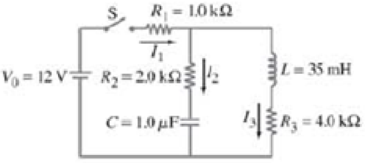
FIGURE 30–30 Problem 73.
Expert Solution & Answer
Want to see the full answer?
Check out a sample textbook solution
Students have asked these similar questions
Cam mechanisms are used in many machines. For example, cams open and close the valves in your car engine to admit gasoline vapor to each cylinder and to allow the escape of exhaust.
The principle is illustrated in the figure below, showing a follower rod (also called a pushrod) of mass m resting on a wedge of mass M. The sliding wedge duplicates the function of a
rotating eccentric disk on a camshaft in your car. Assume that there is no friction between the wedge and the base, between the pushrod and the wedge, or between the rod and the guide
through which it slides. When the wedge is pushed to the left by the force F, the rod moves upward and does something such as opening a valve. By varying the shape of the wedge, the
motion of the follower rod could be made quite complex, but assume that the wedge makes a constant angle of 0 = 15.0°. Suppose you want the wedge and the rod to start from rest and
move with constant acceleration, with the rod moving upward 1.00 mm in 8.00 ms. Take m…
No chatgpt pls will upvote
No chatgpt pls will upvote
Chapter 30 Solutions
Physics for Scientists and Engineers with Modern Physics
Ch. 30.1 - Prob. 1AECh. 30.1 - Prob. 1BECh. 30.3 - Prob. 1CECh. 30.4 - Show that L/R does have dimensions of lime. (See...Ch. 30.4 - Prob. 1EECh. 30.5 - Return to the Chapter-Opening Question, page 785,...Ch. 30.7 - At what frequency is the reactance of a 1.0-F...Ch. 30.7 - Prob. 1HECh. 30 - Prob. 1QCh. 30 - Prob. 2Q
Ch. 30 - Prob. 3QCh. 30 - Prob. 4QCh. 30 - If you are given a fixed length of wire, how would...Ch. 30 - Prob. 6QCh. 30 - Prob. 7QCh. 30 - Prob. 8QCh. 30 - What keeps an LC circuit oscillating even after...Ch. 30 - Is the ac current in the indicator always the same...Ch. 30 - Prob. 11QCh. 30 - In an ac LRC circuit, if XL XC, the circuit is...Ch. 30 - Prob. 13QCh. 30 - Under what conditions is the impedance in an LRC...Ch. 30 - Is it possible for the instantaneous power output...Ch. 30 - In an ac LRC circuit, does the power factor, cos,...Ch. 30 - Describe briefly how the frequency of the source...Ch. 30 - Prob. 18QCh. 30 - In an LRC circuit, the current and the voltage in...Ch. 30 - Compare the oscillations or an LRC circuit to the...Ch. 30 - Prob. 1PCh. 30 - Prob. 2PCh. 30 - Prob. 3PCh. 30 - Prob. 4PCh. 30 - (I) If the current in a 280-mH coil changes...Ch. 30 - Prob. 6PCh. 30 - Prob. 7PCh. 30 - Prob. 8PCh. 30 - Prob. 9PCh. 30 - (II) If the outer conductor of a coaxial cable has...Ch. 30 - Prob. 11PCh. 30 - Prob. 12PCh. 30 - Prob. 13PCh. 30 - (II) Ignoring any mutual inductance, what is the...Ch. 30 - (I) The magnetic field inside an air-filled...Ch. 30 - (I) Typical large values for electric and magnetic...Ch. 30 - (II) What is the energy density at the center of a...Ch. 30 - (II) Calculate the magnetic and electric energy...Ch. 30 - Prob. 19PCh. 30 - (II) Determine the total energy stored per unit...Ch. 30 - (II) Determine the total energy stored per unit...Ch. 30 - Prob. 22PCh. 30 - (II) How many time constants does it take for the...Ch. 30 - (II) It takes 2.56 ms for the current in an LR...Ch. 30 - Prob. 25PCh. 30 - (II) In the circuit of Fig. 3027, determine the...Ch. 30 - Prob. 27PCh. 30 - Prob. 28PCh. 30 - (II) A 12-V battery has been connected to an LR...Ch. 30 - Prob. 30PCh. 30 - (I) The variable capacitor in the tuner of an AM...Ch. 30 - Prob. 32PCh. 30 - (II) In some experiments, short distances are...Ch. 30 - Prob. 34PCh. 30 - Prob. 35PCh. 30 - Prob. 36PCh. 30 - Prob. 37PCh. 30 - Prob. 38PCh. 30 - (I) At what frequency will a 32.0-mH inductor have...Ch. 30 - (I) What is the reactance of a 9.2-F capacitor at...Ch. 30 - (I) Plot a graph of the reactance of a 1.0-F...Ch. 30 - (I) Calculate the reactance of, and rms current...Ch. 30 - (II) A resistor R is in parallel with a capacitor...Ch. 30 - Prob. 44PCh. 30 - (II) (a) What is the reactance of a 0.086-F...Ch. 30 - Prob. 46PCh. 30 - (II) A current I = 1.80 cos 377t (I in amps, t in...Ch. 30 - (I) A 10.0-k resistor is in series with a 26.0-mH...Ch. 30 - (I) A 75- resistor and a 6.8-F capacitor are...Ch. 30 - (I) For a 120-V, 60-Hz voltage, a current of 70 mA...Ch. 30 - (II) A 2.5-k resistor in series with a 420-mH...Ch. 30 - (II) (a) What is the rms current in a series RC...Ch. 30 - (II) An ac voltage source is connected in series...Ch. 30 - (II) Determine the total impedance, phase angle,...Ch. 30 - (II) (a) What is the rms current in a series LR...Ch. 30 - (II) A 35-mH inductor with 2.0- resistance is...Ch. 30 - (II) A 25-mH coil whose resistance is 0.80 is...Ch. 30 - (II) A 75-W lightbulb is designed to operate with...Ch. 30 - (II) In the LRC circuit or Fig. 3019, suppose I =...Ch. 30 - (II) An LRC series circuit with R = 150 , L = 25...Ch. 30 - (II) An LR circuit can be used as a phase shifter....Ch. 30 - (I) A 3800-pF capacitor is connected in series to...Ch. 30 - (I) What is the resonant frequency of the LRC...Ch. 30 - (II) An LRC circuit has L = 4.15 mH and R = 3.80...Ch. 30 - (II) The frequency of the ac voltage source (peak...Ch. 30 - (II) Capacitors made from piezoelectric materials...Ch. 30 - (II) (a) Determine a formula for the average power...Ch. 30 - (II) (a) Show that oscillation of charge Q on the...Ch. 30 - (II) A resonant circuit using a 220-nF capacitor...Ch. 30 - Prob. 70PCh. 30 - Prob. 71GPCh. 30 - Prob. 72GPCh. 30 - At time t = 0, the switch in the circuit shown in...Ch. 30 - Prob. 74GPCh. 30 - Prob. 75GPCh. 30 - Assuming the Earths magnetic field averages about...Ch. 30 - (a) For an underdamped LRC circuit, determine a...Ch. 30 - An electronic device needs to be protected against...Ch. 30 - Prob. 79GPCh. 30 - Prob. 80GPCh. 30 - An ac voltage source V=V0sin(t+90) is connected...Ch. 30 - A circuit contains two elements, but it is not...Ch. 30 - A 3.5-k resistor in series with a 440-mH inductor...Ch. 30 - (a) What is the rms current in on RC circuit if R...Ch. 30 - An inductance coil draws 2.5 A de when connected...Ch. 30 - The Q-value of a resonance circuit can be defined...Ch. 30 - Show that the fraction of electromagnetic energy...Ch. 30 - In a series LRC circuit, the inductance is 33mH,...Ch. 30 - Prob. 89GPCh. 30 - A voltage V = 0.95 sin 754t is applied to an LRC...Ch. 30 - Filler circuit. Figure 3033 shows a simple filler...Ch. 30 - Show that if the inductor L in the filter circuit...Ch. 30 - A resistor R, capacitor C, and inductor L are...Ch. 30 - Suppose a series LRC circuit has two resisiors, R1...Ch. 30 - Prob. 95GPCh. 30 - Prob. 96GPCh. 30 - You have a small electromagnet that consumes 350 W...Ch. 30 - An inductor L in series with a resistor R, driven...Ch. 30 - In a certain LRC series circuit, when the ac...Ch. 30 - Prob. 100GPCh. 30 - Prob. 101GPCh. 30 - For the circuit shown in Fig. 3038, show that if...Ch. 30 - (II) The RC circuit shown in Fig. 3039 is called a...Ch. 30 - (II) The RC circuit shown in Fig. 3040 is called a...Ch. 30 - (III) Write a computer program or use a...
Additional Science Textbook Solutions
Find more solutions based on key concepts
Police Captain Jeffers has suffered a myocardial infarction. a. Explain to his (nonmedically oriented) family w...
Human Physiology: An Integrated Approach (8th Edition)
Using the South Atlantic as an example, label the beginning of the normal polarity period C that began 2 millio...
Applications and Investigations in Earth Science (9th Edition)
6. A construction worker with a weight of 850 N stands on a roof that is sloped at 20°. What is the magnitude...
Physics for Scientists and Engineers: A Strategic Approach, Vol. 1 (Chs 1-21) (4th Edition)
Heat lamps are commonly used to maintain foods at about 50C for as long as 12 hours in cafeteria serving lines....
Microbiology: An Introduction
APPLY 1.2 Express the following quantities in scientific notation
using fundamental SI units of mass and lengt...
Chemistry (7th Edition)
What are four functions of connective tissue?
Anatomy & Physiology (6th Edition)
Knowledge Booster


Learn more about
Need a deep-dive on the concept behind this application? Look no further. Learn more about this topic, physics and related others by exploring similar questions and additional content below.Similar questions
- No chatgpt plsarrow_forwardA rectangular current loop (a = 15.0 cm, b = 34.0 cm) is located a distance d = 10.0 cm near a long, straight wire that carries a current (Iw) of 17.0 A (see the drawing). The current in the loop is IL = 21.0 A. Determine the magnitude of the net magnetic force that acts on the loop. Solve in N. a b IL Iwarrow_forwardTwo long, straight wires are separated by distance, d = 22.0 cm. The wires carry currents of I1 = 7.50 A and I2 = 5.50 A in opposite directions, as shown in the figure. Find the magnitude of the net magnetic field at point (B). Let r₁ = 12.0 cm, r2 = 7.00 cm, and r3 = 13.0 cm. Solve in T. 12 d A √3arrow_forward
- I tried to solve this question, and I had an "expert" answer it and they got it wrong. I cannot answer this questionarrow_forwardEddie Hall is the current world record holder in the deadlift, a powerlifting maneuver in which a weighted barbell is lifted from the ground to waist height, then dropped. The figure below shows a side view of the initial and final positions of the deadlift. a 0 = 55.0° Fift h22.5 cm i hy = 88.0 cm b iarrow_forwardsolve for (_) Narrow_forward
- Two boxes of fruit on a frictionless horizontal surface are connected by a light string as in the figure below, where m₁ = 11 kg and m₂ = 25 kg. A force of F = 80 N is applied to the 25-kg box. mq m1 Applies T Peaches i (a) Determine the acceleration of each box and the tension in the string. acceleration of m₁ acceleration of m₂ tension in the string m/s² m/s² N (b) Repeat the problem for the case where the coefficient of kinetic friction between each box and the surface is 0.10. acceleration of m₁ acceleration of m₂ tension in the string m/s² m/s2 Narrow_forwardAll correct but t1 and t2 from part Aarrow_forwardThree long, straight wires are mounted on the vertices of an equilateral triangle as shown in the figure. The wires carry currents of I₁ = 3.50 A, I2 = 5.50 A, and I3 = 8.50 A. Each side of the triangle has a length of 34.0 cm, and the point (A) is located half way between (11) and (12) along one of the sides. Find the magnitude of the magnetic field at point (A). Solve in Teslas (T). I₁arrow_forward
- Number There are four charges, each with a magnitude of 2.38 μC. Two are positive and two are negative. The charges are fixed to the corners of a 0.132-m square, one to a corner, in such a way that the net force on any charge is directed toward the center of the square. Find the magnitude of the net electrostatic force experienced by any charge. ips que Mi Units estic re harrow_forwardTwo long, straight wires are separated by distance, d = 22.0 cm. The wires carry currents of I1 = 7.50 A and I2 = 5.50 A in opposite directions, as shown in the figure. Find the magnitude of the net magnetic field at point (B). Let r₁ = 12.0 cm, r2 = 7.00 cm, and r3 = 13.0 cm. Solve in T. 12 d A √3arrow_forwardThank you in advance, image with question is attached below.arrow_forward
arrow_back_ios
SEE MORE QUESTIONS
arrow_forward_ios
Recommended textbooks for you

 Physics for Scientists and Engineers: Foundations...PhysicsISBN:9781133939146Author:Katz, Debora M.Publisher:Cengage Learning
 Principles of Physics: A Calculus-Based TextPhysicsISBN:9781133104261Author:Raymond A. Serway, John W. JewettPublisher:Cengage Learning
 Glencoe Physics: Principles and Problems, Student...PhysicsISBN:9780078807213Author:Paul W. ZitzewitzPublisher:Glencoe/McGraw-Hill
 College PhysicsPhysicsISBN:9781305952300Author:Raymond A. Serway, Chris VuillePublisher:Cengage Learning
 College PhysicsPhysicsISBN:9781285737027Author:Raymond A. Serway, Chris VuillePublisher:Cengage Learning
Physics for Scientists and Engineers: Foundations...
Physics
ISBN:9781133939146
Author:Katz, Debora M.
Publisher:Cengage Learning
Principles of Physics: A Calculus-Based Text
Physics
ISBN:9781133104261
Author:Raymond A. Serway, John W. Jewett
Publisher:Cengage Learning
Glencoe Physics: Principles and Problems, Student...
Physics
ISBN:9780078807213
Author:Paul W. Zitzewitz
Publisher:Glencoe/McGraw-Hill
College Physics
Physics
ISBN:9781305952300
Author:Raymond A. Serway, Chris Vuille
Publisher:Cengage Learning
College Physics
Physics
ISBN:9781285737027
Author:Raymond A. Serway, Chris Vuille
Publisher:Cengage Learning
Ohm's law Explained; Author: ALL ABOUT ELECTRONICS;https://www.youtube.com/watch?v=PV8CMZZKrB4;License: Standard YouTube License, CC-BY