
Fluid Mechanics, 8 Ed
8th Edition
ISBN: 9789385965494
Author: Frank White
Publisher: MCGRAW-HILL HIGHER EDUCATION
expand_more
expand_more
format_list_bulleted
Concept explainers
Videos
Textbook Question
Chapter 3, Problem 3.45P
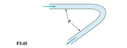
Water enters and leaves the 6-cm-diameter pipe bend in Fig. P3.45 at an average velocity of 8.5 m/s. The horizontal force to support the bend against momentum change is 300 N. Find (a) the angle
Expert Solution & Answer

Trending nowThis is a popular solution!

Students have asked these similar questions
Please do not use any AI tools to solve this question.
I need a fully manual, step-by-step solution with clear explanations, as if it were done by a human tutor.
No AI-generated responses, please.
Please do not use any AI tools to solve this question.
I need a fully manual, step-by-step solution with clear explanations, as if it were done by a human tutor.
No AI-generated responses, please.
[Q2]: The cost information supplied by the cost accountant is as follows:Sales 20,00 units, $ 10 per unitCalculate the (a/ newsale guantity and (b) new selling price to earn the sameVariable cost $ 6 per unit, Fixed Cost $ 30,000, Profit $ 50,000profit ifi) Variable cost increases by $ 2 per unitil) Fixed cost increase by $ 10,000Ili) Variable cost increase by $ 1 per unit and fixed cost reduces by $ 10,000
Chapter 3 Solutions
Fluid Mechanics, 8 Ed
Ch. 3 - Prob. 3.1PCh. 3 - Consider the angular momentum relation in the form...Ch. 3 - For steady low-Reynolds-number (laminar) flow...Ch. 3 - Water at 20°C flows through a long elliptical duct...Ch. 3 - Water at 20°C flows through a 5-in-diameter smooth...Ch. 3 - Water fills a cylindrical tank to depth h. The...Ch. 3 - A spherical tank, of diameter 35 cm, is leaking...Ch. 3 - Three pipes steadily deliver water at 20°C to a...Ch. 3 - A laboratory test tank contains seawater of...Ch. 3 - Water flowing through an 8-cm-diameter pipe enters...
Ch. 3 - Water flows from a faucet into a sink at 3 U.S....Ch. 3 - The pipe flow in Fig, P3.12 fills a cylindrical...Ch. 3 - The cylindrical container in Fig. P3.13 is 20 cm...Ch. 3 - The open tank in Fig. F3.14 contains water at 20°C...Ch. 3 - Water, assumed incompressible, flows steadily...Ch. 3 - P3.16 An incompressible fluid flows past an...Ch. 3 - Incompressible steady flow in the inlet between...Ch. 3 - Gasoline enters section 1 in Fig, P3.18 at 0.5...Ch. 3 - Water from a storm drain flows over an outfall...Ch. 3 - Oil (SG = 0.89) enters at section 1 in Fig, P3.20...Ch. 3 - Prob. 3.21PCh. 3 - Prob. 3.22PCh. 3 - Prob. 3.23PCh. 3 - Prob. 3.24PCh. 3 - Prob. 3.25PCh. 3 - A thin layer of liquid, draining from an inclined...Ch. 3 - Prob. 3.27PCh. 3 - Prob. 3.28PCh. 3 - Prob. 3.29PCh. 3 - Prob. 3.30PCh. 3 - Prob. 3.31PCh. 3 - Prob. 3.32PCh. 3 - In some wind tunnels the test section is...Ch. 3 - A rocket motor is operati ng steadily, as shown in...Ch. 3 - In contrast to the liquid rocket in Fig. P3.34,...Ch. 3 - The jet pump in Fig. P3.36 injects water at U1 =...Ch. 3 - Prob. 3.37PCh. 3 - Prob. 3.38PCh. 3 - A wedge splits a sheet of 20°C water, as shown in...Ch. 3 - The water jet in Fig, P3,40 strikes normal to a...Ch. 3 - P3.41 In Fig. P3.41 the vane turns the water jet...Ch. 3 - Prob. 3.42PCh. 3 - P3.43 Water at 20°C flows through a 5-cm-diameter...Ch. 3 - P3.44 When a uniform stream flows past an immersed...Ch. 3 - Water enters and leaves the 6-cm-diameter pipe...Ch. 3 - When a jet strikes an inclined fixed plate, as in...Ch. 3 - A liquid jet of velocity Vjand diameter Djstrikes...Ch. 3 - The small boat in Fig. P3.48 is driven at a steady...Ch. 3 - The horizontal nozzle in Fig. P3.49 has D1 = 12 in...Ch. 3 - Prob. 3.50PCh. 3 - P3.51 A liquid jet of velocity Vj and area Aj...Ch. 3 - A large commercial power washer delivers 21...Ch. 3 - Prob. 3.53PCh. 3 - For the pipe-flow-reducing section of Fig. P3.54,...Ch. 3 - In Fig. P3.55 the jet strikes a vane that moves to...Ch. 3 - Prob. 3.56PCh. 3 - Prob. 3.57PCh. 3 - Prob. 3.58PCh. 3 - Prob. 3.59PCh. 3 - Prob. 3.60PCh. 3 - Prob. 3.61PCh. 3 - P3.62 Water at 20°C exits to the standard...Ch. 3 - Water flows steadily through the box in Fig....Ch. 3 - The 6-cm-diameter 20°C water jet in Fig. P3.64...Ch. 3 - Prob. 3.65PCh. 3 - Prob. 3.66PCh. 3 - Prob. 3.67PCh. 3 - Prob. 3.68PCh. 3 - P3.69 A uniform rectangular plate, 40 cm long and...Ch. 3 - Prob. 3.70PCh. 3 - Prob. 3.71PCh. 3 - When immersed in a uniform stream, a thick...Ch. 3 - P3.73 A pump in a tank of water at 20°C directs a...Ch. 3 - P3.74 Water at 20°C flows down through a vertical,...Ch. 3 - Prob. 3.75PCh. 3 - Prob. 3.76PCh. 3 - Prob. 3.77PCh. 3 - Prob. 3.78PCh. 3 - P3.79 The Saturn V rocket in the chapter opener...Ch. 3 - Prob. 3.80PCh. 3 - Prob. 3.81PCh. 3 - Prob. 3.82PCh. 3 - Prob. 3.83PCh. 3 - Air at 20°C and 1 atm flows in a 25-cm-diameter...Ch. 3 - Prob. 3.85PCh. 3 - Prob. 3.86PCh. 3 - Prob. 3.87PCh. 3 - Prob. 3.88PCh. 3 - Prob. 3.89PCh. 3 - Prob. 3.90PCh. 3 - Prob. 3.91PCh. 3 - Prob. 3.92PCh. 3 - Prob. 3.93PCh. 3 - A water jet 3 in in diameter strikes a concrete...Ch. 3 - P3.95 A tall water tank discharges through a...Ch. 3 - Prob. 3.96PCh. 3 - Prob. 3.97PCh. 3 - Prob. 3.98PCh. 3 - Prob. 3.99PCh. 3 - Prob. 3.100PCh. 3 - Prob. 3.101PCh. 3 - Prob. 3.102PCh. 3 - Suppose that the solid-propellant rocket of Prob....Ch. 3 - A rocket is attached to a rigid horizontal rod...Ch. 3 - Extend Prob. P3.104 to the case where the rocket...Ch. 3 - Actual airflow past a parachute creates a variable...Ch. 3 - Prob. 3.107PCh. 3 - Prob. 3.108PCh. 3 - Prob. 3.109PCh. 3 - Prob. 3.110PCh. 3 - Prob. 3.111PCh. 3 - A jet of alcohol strikes the vertical plate in...Ch. 3 - Prob. 3.113PCh. 3 - Prob. 3.114PCh. 3 - Prob. 3.115PCh. 3 - P3.116 For the container of Fig. P3.116 use...Ch. 3 - Water at 20°C, in the pressurized tank of Fig....Ch. 3 - P3.118 Bernoulli's 1738 treatise Hydrodynamica...Ch. 3 - Prob. 3.119PCh. 3 - Prob. 3.120PCh. 3 - Prob. 3.121PCh. 3 - Prob. 3.122PCh. 3 - The air-cushion vehicle in Fig, P3.123 brings in...Ch. 3 - Prob. 3.124PCh. 3 - Prob. 3.125PCh. 3 - Prob. 3.126PCh. 3 - Prob. 3.127PCh. 3 - Prob. 3.128PCh. 3 - Prob. 3.129PCh. 3 -
P3.130 In Fig. P3.130 the fluid is gasoline at...Ch. 3 - Prob. 3.131PCh. 3 - Prob. 3.132PCh. 3 - Prob. 3.133PCh. 3 - Prob. 3.134PCh. 3 - Prob. 3.135PCh. 3 - Air, assumed frictionless, flows through a tube,...Ch. 3 - In Fig. P3.137 the piston drives water at 20°C....Ch. 3 - Prob. 3.138PCh. 3 - Prob. 3.139PCh. 3 - Prob. 3.140PCh. 3 - Prob. 3.141PCh. 3 - Prob. 3.142PCh. 3 - Prob. 3.143PCh. 3 - Prob. 3.144PCh. 3 - Prob. 3.145PCh. 3 - The pump in Fig. P3.146 draws gasoline at 20°C...Ch. 3 - The very large water tank in Fig. P3.147 is...Ch. 3 - Prob. 3.148PCh. 3 - P3.149 The horizontal lawn sprinkler in Fig....Ch. 3 - Prob. 3.150PCh. 3 - Prob. 3.151PCh. 3 - Prob. 3.152PCh. 3 - Prob. 3.153PCh. 3 - Prob. 3.154PCh. 3 - Prob. 3.155PCh. 3 - Prob. 3.156PCh. 3 - Prob. 3.157PCh. 3 - Prob. 3.158PCh. 3 - Prob. 3.159PCh. 3 - Prob. 3.160PCh. 3 - Prob. 3.161PCh. 3 - The waterwheel in Fig. P3.162 is being driven at...Ch. 3 - Prob. 3.163PCh. 3 - Prob. 3.164PCh. 3 - Prob. 3.165PCh. 3 - A power plant on a river, as in Fig. P3.166, must...Ch. 3 - Prob. 3.167PCh. 3 - Prob. 3.168PCh. 3 - P3.169 When the pump in Fig. P3.169 draws 220 m3/h...Ch. 3 - Prob. 3.170PCh. 3 - P3.171 Consider a turbine extracting energy from a...Ch. 3 - Prob. 3.172PCh. 3 - Prob. 3.173PCh. 3 - Prob. 3.174PCh. 3 - Prob. 3.175PCh. 3 - Prob. 3.176PCh. 3 - Prob. 3.177PCh. 3 - Prob. 3.178PCh. 3 - Prob. 3.179PCh. 3 - Prob. 3.180PCh. 3 - Prob. 3.181PCh. 3 - Prob. 3.182PCh. 3 - Prob. 3.183PCh. 3 - The large turbine in Fig. P3.184 diverts the river...Ch. 3 - Prob. 3.185PCh. 3 - Prob. 3.1WPCh. 3 - Prob. 3.2WPCh. 3 - Prob. 3.3WPCh. 3 - Prob. 3.4WPCh. 3 - W3.5 Consider a long sewer pipe, half full of...Ch. 3 - Put a table tennis ball in a funnel, and attach...Ch. 3 - How does a siphon work? Are there any limitations...Ch. 3 - Prob. 3.1FEEPCh. 3 - Prob. 3.2FEEPCh. 3 - In Fig, FE3.1 water exits from a nozzle into...Ch. 3 - Prob. 3.4FEEPCh. 3 - Prob. 3.5FEEPCh. 3 - FE3.6 A fireboat pump delivers water to a...Ch. 3 - A fireboat pump delivers water to a vertical...Ch. 3 - Prob. 3.8FEEPCh. 3 - Water flowing in a smooth 6-cm-diameter pipe...Ch. 3 - Prob. 3.10FEEPCh. 3 - In a certain industrial process, oil of density ...Ch. 3 - Prob. 3.2CPCh. 3 - Prob. 3.3CPCh. 3 - Prob. 3.4CPCh. 3 - Prob. 3.5CPCh. 3 - Prob. 3.1DP
Knowledge Booster


Learn more about
Need a deep-dive on the concept behind this application? Look no further. Learn more about this topic, mechanical-engineering and related others by exploring similar questions and additional content below.Similar questions
- can you please help me perform Visual Inspection and Fractography of the attatched image: Preliminary examination to identify the fracture origin, suspected fatigue striation, and corrosion evidences.arrow_forwardcan you please help[ me conduct Causal Analysis (FTA) on the scenario attatched: FTA diagram which is a fault tree analysis diagram will be used to gain an overview of the entire path of failure from root cause to the top event (i.e., the swing’s detachment) and to identify interactions between misuse, material decay and inspection errors.arrow_forwardhi can you please help me in finding the stress intensity factor using a k-calcluator for the scenario attathced in the images.arrow_forward
- Hi, can you please help me .Identify and justify suitable analytical techniques of the scenario below, bearing in mind the kinds of information being handled to reach a conclusion (methodology). A child swing set was discovered to have failed at the fixing at the top of the chains connecting the seat to the top of the swing set. A 12 mm threaded steel bolt, connecting the shackle to the top beam, failed at the start of the threaded region on the linkage closest to the outside side of the swing set . The linkage and bolts were made of electro galvanised mild steel . The rigid bar chain alternatives and fixings were of the same material and appeared to be fitted in accordance with guidelines. The yield strength of the steel used is 260 MPa and the UTS is 380 MPa. The bolt that failed was threaded using a standard thread with a pitch (distance between threads) of 1.75 mm and a depth of approximately 1.1 mm. The swing set in question had been assigned to ‘toddlers’ with the application of…arrow_forwardHi, can you please define and calculate the failure mode of the linkage that failed on the swing (images added) : A child swing set was discovered to have failed at the fixing at the top of the chains connecting the seat to the top of the swing set. A 12 mm threaded steel bolt, connecting the shackle to the top beam, failed at the start of the threaded region on the linkage closest to the outside side of the swing set . The linkage and bolts were made of electro galvanised mild steel . The rigid bar chain alternatives and fixings were of the same material and appeared to be fitted in accordance with guidelines. The yield strength of the steel used is 260 MPa and the UTS is 380 MPa. The bolt that failed was threaded using a standard thread with a pitch (distance between threads) of 1.75 mm and a depth of approximately 1.1 mm. The swing set in question had been assigned to ‘toddlers’ with the application of a caged-type seat. However, the location was within the play area not…arrow_forwardPage 11-68. The rectangular plate shown is subjected to a uniaxial stress of 2000 psi. Compute the shear stress and the tensile developed on a plane forming an angle of 30° with the longitud axis of the member. (Hint: Assume a cross-sectional area of unity) 2000 psi 2000 psi hparrow_forward
- 11-70. A shear stress (pure shear) of 5000 psi exists on an element. (a) Determine the maximum tensile and compressive stresses caused in the element due to this shear. (b) Sketch the element showing the planes on which the maximum tensile and compressive stresses act.arrow_forward11-20. An aluminum specimen of circular cross section, 0.50 in. in diameter, ruptured under a tensile load of 12,000 lb. The plane of failure was found to be at 48° with a plane perpendicular to the longitudinal axis of the specimen. (a) Compute the shear stress on the failure plane. (b) Compute the maximum tensile stress. (c) Compute the tensile stress on the failure plane. hparrow_forwardA long flat steel bar 13 mm thick and 120 mm wide has semicircular grooves as shown and carries a tensile load of 50 kN Determine the maximum stress if plate r= 8mm r=21mm r=38mmarrow_forward
- Problem 13: F₁ = A =250 N 30% Determine the moment of each of the three forces about point B. F₂ = 300 N 60° 2 m -3 m B 4 m F3=500 Narrow_forward3 kN 3 kN 1.8 kN/m 80 mm B 300 mm D an 1.5 m-1.5 m--1.5 m- PROBLEM 5.47 Using the method of Sec. 5.2, solve Prob. 5.16 PROBLEM 5.16 For the beam and loading shown, determine the maximum normal stress due to bending on a transverse section at C.arrow_forward300 mm 3 kN 3 kN 450 N-m D E 200 mm 300 mm PROBLEM 5.12 Draw the shear and bending-moment diagrams for the beam and loading shown, and determine the maximum absolute value (a) of the shear, (b) of the bending moment.arrow_forward
arrow_back_ios
SEE MORE QUESTIONS
arrow_forward_ios
Recommended textbooks for you
 Elements Of ElectromagneticsMechanical EngineeringISBN:9780190698614Author:Sadiku, Matthew N. O.Publisher:Oxford University Press
 Mechanics of Materials (10th Edition)Mechanical EngineeringISBN:9780134319650Author:Russell C. HibbelerPublisher:PEARSON
 Thermodynamics: An Engineering ApproachMechanical EngineeringISBN:9781259822674Author:Yunus A. Cengel Dr., Michael A. BolesPublisher:McGraw-Hill Education
 Control Systems EngineeringMechanical EngineeringISBN:9781118170519Author:Norman S. NisePublisher:WILEY
 Mechanics of Materials (MindTap Course List)Mechanical EngineeringISBN:9781337093347Author:Barry J. Goodno, James M. GerePublisher:Cengage Learning
 Engineering Mechanics: StaticsMechanical EngineeringISBN:9781118807330Author:James L. Meriam, L. G. Kraige, J. N. BoltonPublisher:WILEY
Elements Of Electromagnetics
Mechanical Engineering
ISBN:9780190698614
Author:Sadiku, Matthew N. O.
Publisher:Oxford University Press
Mechanics of Materials (10th Edition)
Mechanical Engineering
ISBN:9780134319650
Author:Russell C. Hibbeler
Publisher:PEARSON
Thermodynamics: An Engineering Approach
Mechanical Engineering
ISBN:9781259822674
Author:Yunus A. Cengel Dr., Michael A. Boles
Publisher:McGraw-Hill Education
Control Systems Engineering
Mechanical Engineering
ISBN:9781118170519
Author:Norman S. Nise
Publisher:WILEY
Mechanics of Materials (MindTap Course List)
Mechanical Engineering
ISBN:9781337093347
Author:Barry J. Goodno, James M. Gere
Publisher:Cengage Learning
Engineering Mechanics: Statics
Mechanical Engineering
ISBN:9781118807330
Author:James L. Meriam, L. G. Kraige, J. N. Bolton
Publisher:WILEY
Surface Finish Measurement - Skidded VS. Skidless Surface Roughness Measurement; Author: Mitutoyo America Corporation;https://www.youtube.com/watch?v=X7jCTIwVs80;License: Standard Youtube License