
Fluid Mechanics, 8 Ed
8th Edition
ISBN: 9789385965494
Author: Frank White
Publisher: MCGRAW-HILL HIGHER EDUCATION
expand_more
expand_more
format_list_bulleted
Concept explainers
Videos
Textbook Question
Chapter 3, Problem 3.19P
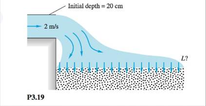
Water from a storm drain flows over an outfall onto a porous bed that absorbs the water at a uniform vertical velocity of 8 mm/s, as shown in Fig. P3.19, The system is 5 m deep into the paper. Find the length L of the bed that will completely absorb the storm water.
Expert Solution & Answer
Want to see the full answer?
Check out a sample textbook solution
Students have asked these similar questions
The resistance R and load effect S for a given failure mode are statistically independent random variables
with marginal PDF's
FR (r) =
0≤r≤100
100'
fs(s)=0.05e0.05, 0
Qu 1 If crank OA rotates with an angular velocity of ω = 12 rad/s, determine the velocity of piston B and
the angular velocity of rod AB at the instant shown.
please show all work
Q2/ Maria has an online shop where she sells hand made paintings and
cards. She sells the painting for 50 and the card for 20. It takes her 2 hours
to complete 1 painting and 45 minutes to make a single card. She also has
a day job and makes paintings and cards in her free time. She cannot spend
more than 15 hours a week to make paintings and cards. Additionally, she
should make not more than 10 paintings and cards per week.
She makes a profit of 25 on painting and 15 on each card. How many
paintings and cards should she make each week to maximize her profit.
Chapter 3 Solutions
Fluid Mechanics, 8 Ed
Ch. 3 - Prob. 3.1PCh. 3 - Consider the angular momentum relation in the form...Ch. 3 - For steady low-Reynolds-number (laminar) flow...Ch. 3 - Water at 20°C flows through a long elliptical duct...Ch. 3 - Water at 20°C flows through a 5-in-diameter smooth...Ch. 3 - Water fills a cylindrical tank to depth h. The...Ch. 3 - A spherical tank, of diameter 35 cm, is leaking...Ch. 3 - Three pipes steadily deliver water at 20°C to a...Ch. 3 - A laboratory test tank contains seawater of...Ch. 3 - Water flowing through an 8-cm-diameter pipe enters...
Ch. 3 - Water flows from a faucet into a sink at 3 U.S....Ch. 3 - The pipe flow in Fig, P3.12 fills a cylindrical...Ch. 3 - The cylindrical container in Fig. P3.13 is 20 cm...Ch. 3 - The open tank in Fig. F3.14 contains water at 20°C...Ch. 3 - Water, assumed incompressible, flows steadily...Ch. 3 - P3.16 An incompressible fluid flows past an...Ch. 3 - Incompressible steady flow in the inlet between...Ch. 3 - Gasoline enters section 1 in Fig, P3.18 at 0.5...Ch. 3 - Water from a storm drain flows over an outfall...Ch. 3 - Oil (SG = 0.89) enters at section 1 in Fig, P3.20...Ch. 3 - Prob. 3.21PCh. 3 - Prob. 3.22PCh. 3 - Prob. 3.23PCh. 3 - Prob. 3.24PCh. 3 - Prob. 3.25PCh. 3 - A thin layer of liquid, draining from an inclined...Ch. 3 - Prob. 3.27PCh. 3 - Prob. 3.28PCh. 3 - Prob. 3.29PCh. 3 - Prob. 3.30PCh. 3 - Prob. 3.31PCh. 3 - Prob. 3.32PCh. 3 - In some wind tunnels the test section is...Ch. 3 - A rocket motor is operati ng steadily, as shown in...Ch. 3 - In contrast to the liquid rocket in Fig. P3.34,...Ch. 3 - The jet pump in Fig. P3.36 injects water at U1 =...Ch. 3 - Prob. 3.37PCh. 3 - Prob. 3.38PCh. 3 - A wedge splits a sheet of 20°C water, as shown in...Ch. 3 - The water jet in Fig, P3,40 strikes normal to a...Ch. 3 - P3.41 In Fig. P3.41 the vane turns the water jet...Ch. 3 - Prob. 3.42PCh. 3 - P3.43 Water at 20°C flows through a 5-cm-diameter...Ch. 3 - P3.44 When a uniform stream flows past an immersed...Ch. 3 - Water enters and leaves the 6-cm-diameter pipe...Ch. 3 - When a jet strikes an inclined fixed plate, as in...Ch. 3 - A liquid jet of velocity Vjand diameter Djstrikes...Ch. 3 - The small boat in Fig. P3.48 is driven at a steady...Ch. 3 - The horizontal nozzle in Fig. P3.49 has D1 = 12 in...Ch. 3 - Prob. 3.50PCh. 3 - P3.51 A liquid jet of velocity Vj and area Aj...Ch. 3 - A large commercial power washer delivers 21...Ch. 3 - Prob. 3.53PCh. 3 - For the pipe-flow-reducing section of Fig. P3.54,...Ch. 3 - In Fig. P3.55 the jet strikes a vane that moves to...Ch. 3 - Prob. 3.56PCh. 3 - Prob. 3.57PCh. 3 - Prob. 3.58PCh. 3 - Prob. 3.59PCh. 3 - Prob. 3.60PCh. 3 - Prob. 3.61PCh. 3 - P3.62 Water at 20°C exits to the standard...Ch. 3 - Water flows steadily through the box in Fig....Ch. 3 - The 6-cm-diameter 20°C water jet in Fig. P3.64...Ch. 3 - Prob. 3.65PCh. 3 - Prob. 3.66PCh. 3 - Prob. 3.67PCh. 3 - Prob. 3.68PCh. 3 - P3.69 A uniform rectangular plate, 40 cm long and...Ch. 3 - Prob. 3.70PCh. 3 - Prob. 3.71PCh. 3 - When immersed in a uniform stream, a thick...Ch. 3 - P3.73 A pump in a tank of water at 20°C directs a...Ch. 3 - P3.74 Water at 20°C flows down through a vertical,...Ch. 3 - Prob. 3.75PCh. 3 - Prob. 3.76PCh. 3 - Prob. 3.77PCh. 3 - Prob. 3.78PCh. 3 - P3.79 The Saturn V rocket in the chapter opener...Ch. 3 - Prob. 3.80PCh. 3 - Prob. 3.81PCh. 3 - Prob. 3.82PCh. 3 - Prob. 3.83PCh. 3 - Air at 20°C and 1 atm flows in a 25-cm-diameter...Ch. 3 - Prob. 3.85PCh. 3 - Prob. 3.86PCh. 3 - Prob. 3.87PCh. 3 - Prob. 3.88PCh. 3 - Prob. 3.89PCh. 3 - Prob. 3.90PCh. 3 - Prob. 3.91PCh. 3 - Prob. 3.92PCh. 3 - Prob. 3.93PCh. 3 - A water jet 3 in in diameter strikes a concrete...Ch. 3 - P3.95 A tall water tank discharges through a...Ch. 3 - Prob. 3.96PCh. 3 - Prob. 3.97PCh. 3 - Prob. 3.98PCh. 3 - Prob. 3.99PCh. 3 - Prob. 3.100PCh. 3 - Prob. 3.101PCh. 3 - Prob. 3.102PCh. 3 - Suppose that the solid-propellant rocket of Prob....Ch. 3 - A rocket is attached to a rigid horizontal rod...Ch. 3 - Extend Prob. P3.104 to the case where the rocket...Ch. 3 - Actual airflow past a parachute creates a variable...Ch. 3 - Prob. 3.107PCh. 3 - Prob. 3.108PCh. 3 - Prob. 3.109PCh. 3 - Prob. 3.110PCh. 3 - Prob. 3.111PCh. 3 - A jet of alcohol strikes the vertical plate in...Ch. 3 - Prob. 3.113PCh. 3 - Prob. 3.114PCh. 3 - Prob. 3.115PCh. 3 - P3.116 For the container of Fig. P3.116 use...Ch. 3 - Water at 20°C, in the pressurized tank of Fig....Ch. 3 - P3.118 Bernoulli's 1738 treatise Hydrodynamica...Ch. 3 - Prob. 3.119PCh. 3 - Prob. 3.120PCh. 3 - Prob. 3.121PCh. 3 - Prob. 3.122PCh. 3 - The air-cushion vehicle in Fig, P3.123 brings in...Ch. 3 - Prob. 3.124PCh. 3 - Prob. 3.125PCh. 3 - Prob. 3.126PCh. 3 - Prob. 3.127PCh. 3 - Prob. 3.128PCh. 3 - Prob. 3.129PCh. 3 -
P3.130 In Fig. P3.130 the fluid is gasoline at...Ch. 3 - Prob. 3.131PCh. 3 - Prob. 3.132PCh. 3 - Prob. 3.133PCh. 3 - Prob. 3.134PCh. 3 - Prob. 3.135PCh. 3 - Air, assumed frictionless, flows through a tube,...Ch. 3 - In Fig. P3.137 the piston drives water at 20°C....Ch. 3 - Prob. 3.138PCh. 3 - Prob. 3.139PCh. 3 - Prob. 3.140PCh. 3 - Prob. 3.141PCh. 3 - Prob. 3.142PCh. 3 - Prob. 3.143PCh. 3 - Prob. 3.144PCh. 3 - Prob. 3.145PCh. 3 - The pump in Fig. P3.146 draws gasoline at 20°C...Ch. 3 - The very large water tank in Fig. P3.147 is...Ch. 3 - Prob. 3.148PCh. 3 - P3.149 The horizontal lawn sprinkler in Fig....Ch. 3 - Prob. 3.150PCh. 3 - Prob. 3.151PCh. 3 - Prob. 3.152PCh. 3 - Prob. 3.153PCh. 3 - Prob. 3.154PCh. 3 - Prob. 3.155PCh. 3 - Prob. 3.156PCh. 3 - Prob. 3.157PCh. 3 - Prob. 3.158PCh. 3 - Prob. 3.159PCh. 3 - Prob. 3.160PCh. 3 - Prob. 3.161PCh. 3 - The waterwheel in Fig. P3.162 is being driven at...Ch. 3 - Prob. 3.163PCh. 3 - Prob. 3.164PCh. 3 - Prob. 3.165PCh. 3 - A power plant on a river, as in Fig. P3.166, must...Ch. 3 - Prob. 3.167PCh. 3 - Prob. 3.168PCh. 3 - P3.169 When the pump in Fig. P3.169 draws 220 m3/h...Ch. 3 - Prob. 3.170PCh. 3 - P3.171 Consider a turbine extracting energy from a...Ch. 3 - Prob. 3.172PCh. 3 - Prob. 3.173PCh. 3 - Prob. 3.174PCh. 3 - Prob. 3.175PCh. 3 - Prob. 3.176PCh. 3 - Prob. 3.177PCh. 3 - Prob. 3.178PCh. 3 - Prob. 3.179PCh. 3 - Prob. 3.180PCh. 3 - Prob. 3.181PCh. 3 - Prob. 3.182PCh. 3 - Prob. 3.183PCh. 3 - The large turbine in Fig. P3.184 diverts the river...Ch. 3 - Prob. 3.185PCh. 3 - Prob. 3.1WPCh. 3 - Prob. 3.2WPCh. 3 - Prob. 3.3WPCh. 3 - Prob. 3.4WPCh. 3 - W3.5 Consider a long sewer pipe, half full of...Ch. 3 - Put a table tennis ball in a funnel, and attach...Ch. 3 - How does a siphon work? Are there any limitations...Ch. 3 - Prob. 3.1FEEPCh. 3 - Prob. 3.2FEEPCh. 3 - In Fig, FE3.1 water exits from a nozzle into...Ch. 3 - Prob. 3.4FEEPCh. 3 - Prob. 3.5FEEPCh. 3 - FE3.6 A fireboat pump delivers water to a...Ch. 3 - A fireboat pump delivers water to a vertical...Ch. 3 - Prob. 3.8FEEPCh. 3 - Water flowing in a smooth 6-cm-diameter pipe...Ch. 3 - Prob. 3.10FEEPCh. 3 - In a certain industrial process, oil of density ...Ch. 3 - Prob. 3.2CPCh. 3 - Prob. 3.3CPCh. 3 - Prob. 3.4CPCh. 3 - Prob. 3.5CPCh. 3 - Prob. 3.1DP
Knowledge Booster


Learn more about
Need a deep-dive on the concept behind this application? Look no further. Learn more about this topic, mechanical-engineering and related others by exploring similar questions and additional content below.Similar questions
- For the beam and loading shown, (a) draw the shear and bending moment diagrams, (b) determine the magnitude and location of the maximum absolute value of the bending momentConsider A = 0please show step by step process, i did something wrong with bending moment diagram( length of beam = 2 + 6 + 2)arrow_forwardCORRECT ANSWER ONLY WITH COMPLETE FBD. PREFERABLY HANDWRITTEN. I WILL UPVOTE 1. The beam shown carries the following loads:Total dead load, wDL = 36 kN/mConcentrated live load, PLL = 240 kNThe beam section is HSS16X12X3/8 with properties:Span, L = 6 mArea, A = 12,100 mm2Moment of inertia about x-axis, Ix = 292 x 106 mm4Fy = 345 MPa 1. Calculate the location of the live load, from the left support, for maximum moment to occur at the fixed support.Answer: 2.536 m2. Calculate the maximum moment. Answer: 439.128 kN-marrow_forwardCORRECT ANSWER AND COMPLETE FBD ONLY. I PREFER HANDWRITTEN BUT ITS OKAY IF NOT. I WILL UPVOTE 2. The space truss shown is supported by ball-and-socket joints at A, B and C. Factored loads P1 and P2 areacting on joints D and E, respectively, towards the negative y-direction. 1. Calculate the stress of member CE, indicate tension or compression. Answer: 23.61 MPa Tension2. Calculate the stress of member AD, indicate tension or compression. Answer: 21.01 MPa Compression3. Calculate the stress of member CD, indicate tension or compression. Answer: 11.03 MPa Tensionarrow_forward
- CORRECT ANSWER AND COMPLETE FBD ONLY. I PREFER HANDWRITTEN BUT ITS OKAY IF NOT. I WILL UPVOTE 3. The frame has pin supports at A and E, subject to a wind load. Treat joint C to be an internal hinge. Given:Dimensions, H1 = 3.0 m; H2 = 4.5 m; L = 10.0 mWind loads, wWL (AB) = 4.8 kN/m; wWL (BC) = 3.9 kN/m; wWL (CD) = 1.5 kN/m; wWL (DE) = 1.2 kN/mMembers are made of A36 steel Wide Flange Section with the following properties:Area, A = 64000 mm2Depth, d = 762 mmFlange width, bf = 371 mmThickness of web, tw = 32 mmThickness of flange, tf = 57.9 mmMoment of inertia about x-axis, Ix = 6080 x 106 mm4The wide flange is oriented so that the bending is about the x-axis1. Calculate the stress in member AB, due to the axial load it carries, indicate if tension or compression.Answer: 0.0476 MPa Tension2. Calculate the stress in member DE, due to the axial load it carries, indicate if tension or compression.Answer: 0.2351 MPa Compression3. Calculate the maximum bending stress at B. Answer: 4.282 MPaarrow_forward32 mm 32 mm b' c' C 32 mm 32 mm b PROBLEM 6.41 a The extruded beam shown has a uniform wall thickness of 3 mm. Knowing that the vertical shear in the beam is 9 kN, determine the shearing stress at each of the five points indicated.arrow_forwardIn a structural reliability problem, the resistance (capacity) R and load effect (demand) S random variables associated with a failure mode of the structure of interest are normally distributed and statistically independent with the following probability distribution parameters (or statistics) in consistent units: MR = 12, σR = 3 μs = 5, σs = 2 (a) Determine the exact probability of failure pF ·arrow_forward
- The resistance R and load effect S for a given failure mode are statistically independent random variables with marginal PDF's 1 fR (r) = 0≤r≤100 100' fs(s)=0.05e-0.05s (a) Determine the probability of failure by computing the probability content of the failure domain defined as {rarrow_forwardPlease solve this problem as soon as possible My ID# 016948724arrow_forwardThe gears shown in the figure have a diametral pitch of 2 teeth per inch and a 20° pressure angle. The pinion rotates at 1800 rev/min clockwise and transmits 200 hp through the idler pair to gear 5 on shaft c. What forces do gears 3 and 4 transmit to the idler shaft? TS I y 18T 32T This a 12 x 18T C 48T 5arrow_forwardQuestion 1. Draw 3 teeth for the following pinion and gear respectively. The teeth should be drawn near the pressure line so that the teeth from the pinion should mesh those of the gear. Drawing scale (1:1). Either a precise hand drawing or CAD drawing is acceptable. Draw all the trajectories of the involute lines and the circles. Specification: 18tooth pinion and 30tooth gear. Diameter pitch=P=6 teeth /inch. Pressure angle:20°, 1/P for addendum (a) and 1.25/P for dedendum (b). For fillet, c=b-a.arrow_forward5. The figure shows a gear train. There is no friction at the bearings except for the gear tooth forces. The material of the milled gears is steel having a Brinell hardness of 170. The input shaft speed (n2) is 800 rpm. The face width and the contact angle for all gears are 1 in and 20° respectively. In this gear set, the endurance limit (Se) is 15 kpsi and nd (design factor) is 2. (a) Find the revolution speed of gear 5. (b) Determine whether each gear satisfies the design factor of 2.0 for bending fatigue. (c) Determine whether each gear satisfies the design factor of 2.0 for surface fatigue (contact stress). (d) According to the computation results of the questions (b) and (c), explain the possible failure mechanisms for each gear. N4=28 800rpm N₁=43 N5=34 N₂=14 P(diameteral pitch)=8 for all gears Coupled to 2.5hp motorarrow_forward1. The rotating steel shaft is simply supported by bearings at points of B and C, and is driven by a spur gear at D, which has a 6-in pitch diameter. The force F from the drive gear acts at a pressure angle of 20°. The shaft transmits a torque to point A of TA =3000 lbĘ in. The shaft is machined from steel with Sy=60kpsi and Sut=80 kpsi. (1) Draw a shear force diagram and a bending moment diagram by F. According to your analysis, where is the point of interest to evaluate the safety factor among A, B, C, and D? Describe the reason. (Hint: To find F, the torque Tд is generated by the tangential force of F (i.e. Ftangential-Fcos20°) When n=2.5, K=1.8, and K₁ =1.3, determine the diameter of the shaft based on (2) static analysis using DE theory (note that fatigue stress concentration factors need to be used for this question because the loading condition is fatigue) and (3) a fatigue analysis using modified Goodman. Note) A standard diameter is not required for the questions. 10 in Darrow_forwardarrow_back_iosSEE MORE QUESTIONSarrow_forward_ios
Recommended textbooks for you
 Principles of Heat Transfer (Activate Learning wi...Mechanical EngineeringISBN:9781305387102Author:Kreith, Frank; Manglik, Raj M.Publisher:Cengage Learning
 International Edition---engineering Mechanics: St...Mechanical EngineeringISBN:9781305501607Author:Andrew Pytel And Jaan KiusalaasPublisher:CENGAGE L
 Refrigeration and Air Conditioning Technology (Mi...Mechanical EngineeringISBN:9781305578296Author:John Tomczyk, Eugene Silberstein, Bill Whitman, Bill JohnsonPublisher:Cengage Learning
 Automotive Technology: A Systems Approach (MindTa...Mechanical EngineeringISBN:9781133612315Author:Jack Erjavec, Rob ThompsonPublisher:Cengage Learning
Principles of Heat Transfer (Activate Learning wi...
Mechanical Engineering
ISBN:9781305387102
Author:Kreith, Frank; Manglik, Raj M.
Publisher:Cengage Learning
International Edition---engineering Mechanics: St...
Mechanical Engineering
ISBN:9781305501607
Author:Andrew Pytel And Jaan Kiusalaas
Publisher:CENGAGE L
Refrigeration and Air Conditioning Technology (Mi...
Mechanical Engineering
ISBN:9781305578296
Author:John Tomczyk, Eugene Silberstein, Bill Whitman, Bill Johnson
Publisher:Cengage Learning
Automotive Technology: A Systems Approach (MindTa...
Mechanical Engineering
ISBN:9781133612315
Author:Jack Erjavec, Rob Thompson
Publisher:Cengage Learning
Surface Finish Measurement - Skidded VS. Skidless Surface Roughness Measurement; Author: Mitutoyo America Corporation;https://www.youtube.com/watch?v=X7jCTIwVs80;License: Standard Youtube License