
Applied Statics and Strength of Materials (6th Edition)
6th Edition
ISBN: 9780133840544
Author: George F. Limbrunner, Craig D'Allaird, Leonard Spiegel
Publisher: PEARSON
expand_more
expand_more
format_list_bulleted
Concept explainers
Videos
Textbook Question
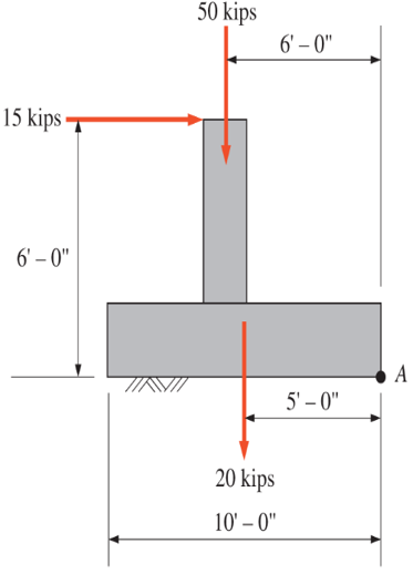
Chapter 3, Problem 3.45P
For the concrete structure shown, determine the magnitude, direction, and sense of the resultant force. Determine where the resultant intersects the bottom of the footing with respect to point A.
Problem 3.45
Expert Solution & Answer

Trending nowThis is a popular solution!

Learn your wayIncludes step-by-step video

schedule04:11
Students have asked these similar questions
determine the magnitude of the resultant of the parallel force system shown. located the resultant with respect to point A. assume that all forces are vertical and that the members are horizontal.
1. The rectangular framework shown in the next slide is subjected to
the indicated non-concurrent system of forces. Determine the
magnitude and direction of the resultant, also its moment arm
relative to the origin O.
Y
15 kips 12 kips
53
10 ft
50
8 kips
7 ft
69
5 kips
13 kips
Q: Determine the resultant of the force system shown in Fig. (1) and
locate it with respect to point A
10 kN
800 KN.m
6 m
10 m
7 IN
Fig. (1)
Chapter 3 Solutions
Applied Statics and Strength of Materials (6th Edition)
Ch. 3 - through 3.3 Determine the magnitude, direction,...Ch. 3 - Determine the magnitude, direction, and sense of...Ch. 3 - Determine the magnitude, direction, and sense of...Ch. 3 - Solve Problem 3.1 through 3.3 using the method of...Ch. 3 - Solve Problem 3.1 through 3.3 using the method of...Ch. 3 - through 3.6 Solve Problem 3.1 through 3.3 using...Ch. 3 - The 150-lb force shown is the resultant of two...Ch. 3 - Find the resultant force P exerted on the tree.Ch. 3 - Find the resultant force R exerted on the pole.Ch. 3 - Calculate the resultant force on the screw eye....
Ch. 3 - Determine the resultant of the coplanar concurrent...Ch. 3 - Use the parallelogram law to find the following...Ch. 3 - Prob. 3.13PCh. 3 - Determine the resultant of the coplanar concurrent...Ch. 3 - The resultant of the concurrent force system shown...Ch. 3 - Three force of 900 lb, 1000 lb, and 600 lb are...Ch. 3 - The four forces shown hade parallel lines of...Ch. 3 - Three coplanar concurrent forces act as shown. a....Ch. 3 - Four coplanar concurrent forces act as shown a....Ch. 3 - Determine the resultant of the four forces of...Ch. 3 - For the concrete wall and footing shown: a....Ch. 3 - Calculate the moment of the 550-lb force about...Ch. 3 - In Problem 3.22 , calculate the moment about point...Ch. 3 - Compute the moment about point A for the linkage...Ch. 3 - Compute the moment of the force F about point A...Ch. 3 - Determine the magnitude of the resultant of the...Ch. 3 - Determine the magnitude of the resultant of the...Ch. 3 - Determine the magnitude of the resultant of the...Ch. 3 - Determine the magnitude of the resultant of the...Ch. 3 - Determine the resultant and its location for the...Ch. 3 - Compute the magnitude, sense, and location of the...Ch. 3 - Compute the magnitude, sense, and location of the...Ch. 3 - Compute the magnitude and location of the...Ch. 3 - Determine the magnitude and location of the...Ch. 3 - Fresh water is impounded behind a dam to a height...Ch. 3 - Determine the magnitude and location of the...Ch. 3 - Determine the magnitude and location of the...Ch. 3 - Compute the magnitude and direction of the...Ch. 3 - Compute the magnitude and direction of the...Ch. 3 - Compute the magnitude and direction of the...Ch. 3 - A body is subjected to the following three...Ch. 3 - Determine the magnitude, direction, and sense of...Ch. 3 - Determine the magnitude, direction, and sense of...Ch. 3 - Determine the resultant of the load system shown....Ch. 3 - For the concrete structure shown, determine the...Ch. 3 - For the following computer problems, any...Ch. 3 - For the following computer problems, any...Ch. 3 - For the following computer problems, any...Ch. 3 - 3.49 Determine the magnitude, direction, and sense...Ch. 3 - The resultant and one-component force of a...Ch. 3 - The resultant force of a concurrent force system...Ch. 3 - Determine the magnitudes of forces P1 and P2 such...Ch. 3 - The resultant force of a concurrent force system...Ch. 3 - A hockey puck is acted on simultaneously by two...Ch. 3 - Determine the resultant force for each of the...Ch. 3 - Determine the resultant force for each of the...Ch. 3 - The resultant of the three concurrent forces shown...Ch. 3 - The transmission tower shown is subjected to a...Ch. 3 - A gravity-type masonry dam, as shown, depends on...Ch. 3 - The transfomer (as shown) must be lifted...Ch. 3 - Refer to the diagram for Problem 3.60 /. Assume...Ch. 3 - The plastic barrel tent anchor of Problem 2.11...Ch. 3 - Calculate the moment of the forces shown with...Ch. 3 - Determine the magnitude and location of the...Ch. 3 - Determine the moment (about point A) of the appied...Ch. 3 - The lift force on the wing of an aircraft is...Ch. 3 - A beam is subjected to distributed loads as shown....Ch. 3 - For the concrete gravity wall shown, determine the...Ch. 3 - Fresh water is impounded to a height of 8 ft...Ch. 3 - Plank, 2 in. by 10 in. in cross section and 5 ft...Ch. 3 - a. Compute the moment (about point A) of the...Ch. 3 - Determine the resultant of the three forces acting...Ch. 3 - a. Calculate the moments about points A and B due...Ch. 3 - Determine the magnitude of F1 and F2 shown such...Ch. 3 - Calculate the magnitude, direction, and sense of...
Additional Engineering Textbook Solutions
Find more solutions based on key concepts
ICA 8-57
A 100-watt [W] motor (60% efficient) is available to raise a load 5 meters [m] into the air. If the ta...
Thinking Like an Engineer: An Active Learning Approach (4th Edition)
The moment of the force F about an axis extending between A and C.
Engineering Mechanics: Statics & Dynamics (14th Edition)
What parts are included in the vehicle chassis?
Automotive Technology: Principles, Diagnosis, And Service (6th Edition) (halderman Automotive Series)
1.1 What is the difference between an atom and a molecule? A molecule and a crystal?
Manufacturing Engineering & Technology
Determine the reactions at the supports A and B, then draw the shear and moment diagram. El is constant. Neglec...
Mechanics of Materials
Calculate the mass of 1ft3 of gasoline if it weighs 42.0 lb.
Applied Fluid Mechanics (7th Edition)
Knowledge Booster


Learn more about
Need a deep-dive on the concept behind this application? Look no further. Learn more about this topic, mechanical-engineering and related others by exploring similar questions and additional content below.Similar questions
- The pole OB is subjected to the 6004b force at B. Determine (a) the rectangular components of the force; and (b) the angles between the force vector and the coordinate axes.arrow_forwardFind the internal force systems acting on sections 1 and 2.arrow_forwardPROBLEM 3. Determine the resultant of the force system acting on the beam shown and find where it intersects the beam measured from point 0. 8 kN/m SUMMARY OF ANSWERS 5 kN/m R 1.5 m 0.75 m- 0.75 m-arrow_forward
- Problem (2): Determine the magnitude and direction of P so that the resultant of P and the 900-N force is a vertical force of 2700-N directed downward.arrow_forwardFind the resultant force for the forces shown by (a) using the parallelogram law and (b) by resolving the forcees into their x and y components.arrow_forwarddetermine the magnitude of the resultant of the parallel force systems shown. locate the resultant with respect to point A. assume that all forces are vertical and that the members are horizontal.arrow_forward
- 1. Determine the magnitude of the resultant of the parallel force system shown below. Locate the resultant with respect to point A. Assume that all forces are vertical and that the members are horizontal. 5 kips 3 kips 3'-0" A Answer: (1) Resultant: (2) Location: 3'-0" 8 kips + 5'-0" 12 kips 2'-0" 2 kipsarrow_forwardThe portion of a bridge truss is subjected to several loads. For the loading shown, determine the location in the r-z plane through which the resultant passes as well as R, the resultant force. + Narrative 3 m 3 m 3 m 3 m 4 m 75 kN 1.5 m 250 kN 3 m 100 kN 120 kNarrow_forwardPart II: Determine the magnitude of force F3 if the resultant of all three forces is directly above the support at B. F=100 lb. 4' 6' F₂=200 lb. 6' 6' Carrow_forward
- Determine the magnitude of the resultant force F(R). Determine the angle between the resultant force and the x axis. And finally specify where the resultant’s line of action intersects member AB, measured from point A. (y = ….. ft above A)arrow_forwarddetermine the magnitude and location of the resultant force for the load system shownarrow_forwarddetermine the magnitude, direction, and sense of teh resultant force of the nonconcurrent force system shown. located the resultant with respect to point O.arrow_forward
arrow_back_ios
SEE MORE QUESTIONS
arrow_forward_ios
Recommended textbooks for you
 International Edition---engineering Mechanics: St...Mechanical EngineeringISBN:9781305501607Author:Andrew Pytel And Jaan KiusalaasPublisher:CENGAGE L
International Edition---engineering Mechanics: St...
Mechanical Engineering
ISBN:9781305501607
Author:Andrew Pytel And Jaan Kiusalaas
Publisher:CENGAGE L
Hand Tools; Author: UCI Media;https://www.youtube.com/watch?v=4o0tqF0jDdo;License: Standard Youtube License