
Applied Statics and Strength of Materials (6th Edition)
6th Edition
ISBN: 9780133840544
Author: George F. Limbrunner, Craig D'Allaird, Leonard Spiegel
Publisher: PEARSON
expand_more
expand_more
format_list_bulleted
Concept explainers
Videos
Textbook Question
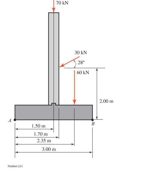
Chapter 3, Problem 3.21P
For the concrete wall and footing shown:
a. Calculate the algebraic summation of the moments of the forces shown about point A.
b. Calculate the algebraic summation of the moments of the forces about point B.
Expert Solution & Answer

Learn your wayIncludes step-by-step video

schedule03:30
Students have asked these similar questions
Problem 4. Use the parallelogram of forces method to
find the magnitude and direction of the resultant of a
force of 250 N acting at an angle of 135° and a force of
400 N acting at an angle of -120°
1: A force of 105 N is applied at O. Determine its component forces along n and y axes. Also calculate the component forces along x and t axes.
For the structures loaded as shown, calculate the moment produced by forces about points A, B and C. The uniform load in ( a ) is perpendicular to the inclined member. Each square in ( b ) has a dimension of 1 m x 1 m.
In the assembly shown, member AB is rigidly attached to the wall while an L bar is pinned to AB at E. Two forces P and Q are acting on the assembly as shown. Force P lies on the x-axis while force Q is applied at point D along a plane parallel to the yz plane.
1. Which of the following quantities is/are zero? (Choices: A. Moment of P about the x-axis ; B. Moment of P about the y-axis ; C. Moment of P about the z-axis) 2. Which of the following best approximates the moment of force Q about point A?
3. Which of the following best approximates the equivalent force-couple set at point A of the applied forces P and Q? Note: F is the resultant force and Cis the resultant couple4. Considering the force diagram of member DE, which gives the complete set of reactions for the support at E? (Note difference of Force and couple reactions)
Chapter 3 Solutions
Applied Statics and Strength of Materials (6th Edition)
Ch. 3 - through 3.3 Determine the magnitude, direction,...Ch. 3 - Determine the magnitude, direction, and sense of...Ch. 3 - Determine the magnitude, direction, and sense of...Ch. 3 - Solve Problem 3.1 through 3.3 using the method of...Ch. 3 - Solve Problem 3.1 through 3.3 using the method of...Ch. 3 - through 3.6 Solve Problem 3.1 through 3.3 using...Ch. 3 - The 150-lb force shown is the resultant of two...Ch. 3 - Find the resultant force P exerted on the tree.Ch. 3 - Find the resultant force R exerted on the pole.Ch. 3 - Calculate the resultant force on the screw eye....
Ch. 3 - Determine the resultant of the coplanar concurrent...Ch. 3 - Use the parallelogram law to find the following...Ch. 3 - Prob. 3.13PCh. 3 - Determine the resultant of the coplanar concurrent...Ch. 3 - The resultant of the concurrent force system shown...Ch. 3 - Three force of 900 lb, 1000 lb, and 600 lb are...Ch. 3 - The four forces shown hade parallel lines of...Ch. 3 - Three coplanar concurrent forces act as shown. a....Ch. 3 - Four coplanar concurrent forces act as shown a....Ch. 3 - Determine the resultant of the four forces of...Ch. 3 - For the concrete wall and footing shown: a....Ch. 3 - Calculate the moment of the 550-lb force about...Ch. 3 - In Problem 3.22 , calculate the moment about point...Ch. 3 - Compute the moment about point A for the linkage...Ch. 3 - Compute the moment of the force F about point A...Ch. 3 - Determine the magnitude of the resultant of the...Ch. 3 - Determine the magnitude of the resultant of the...Ch. 3 - Determine the magnitude of the resultant of the...Ch. 3 - Determine the magnitude of the resultant of the...Ch. 3 - Determine the resultant and its location for the...Ch. 3 - Compute the magnitude, sense, and location of the...Ch. 3 - Compute the magnitude, sense, and location of the...Ch. 3 - Compute the magnitude and location of the...Ch. 3 - Determine the magnitude and location of the...Ch. 3 - Fresh water is impounded behind a dam to a height...Ch. 3 - Determine the magnitude and location of the...Ch. 3 - Determine the magnitude and location of the...Ch. 3 - Compute the magnitude and direction of the...Ch. 3 - Compute the magnitude and direction of the...Ch. 3 - Compute the magnitude and direction of the...Ch. 3 - A body is subjected to the following three...Ch. 3 - Determine the magnitude, direction, and sense of...Ch. 3 - Determine the magnitude, direction, and sense of...Ch. 3 - Determine the resultant of the load system shown....Ch. 3 - For the concrete structure shown, determine the...Ch. 3 - For the following computer problems, any...Ch. 3 - For the following computer problems, any...Ch. 3 - For the following computer problems, any...Ch. 3 - 3.49 Determine the magnitude, direction, and sense...Ch. 3 - The resultant and one-component force of a...Ch. 3 - The resultant force of a concurrent force system...Ch. 3 - Determine the magnitudes of forces P1 and P2 such...Ch. 3 - The resultant force of a concurrent force system...Ch. 3 - A hockey puck is acted on simultaneously by two...Ch. 3 - Determine the resultant force for each of the...Ch. 3 - Determine the resultant force for each of the...Ch. 3 - The resultant of the three concurrent forces shown...Ch. 3 - The transmission tower shown is subjected to a...Ch. 3 - A gravity-type masonry dam, as shown, depends on...Ch. 3 - The transfomer (as shown) must be lifted...Ch. 3 - Refer to the diagram for Problem 3.60 /. Assume...Ch. 3 - The plastic barrel tent anchor of Problem 2.11...Ch. 3 - Calculate the moment of the forces shown with...Ch. 3 - Determine the magnitude and location of the...Ch. 3 - Determine the moment (about point A) of the appied...Ch. 3 - The lift force on the wing of an aircraft is...Ch. 3 - A beam is subjected to distributed loads as shown....Ch. 3 - For the concrete gravity wall shown, determine the...Ch. 3 - Fresh water is impounded to a height of 8 ft...Ch. 3 - Plank, 2 in. by 10 in. in cross section and 5 ft...Ch. 3 - a. Compute the moment (about point A) of the...Ch. 3 - Determine the resultant of the three forces acting...Ch. 3 - a. Calculate the moments about points A and B due...Ch. 3 - Determine the magnitude of F1 and F2 shown such...Ch. 3 - Calculate the magnitude, direction, and sense of...
Additional Engineering Textbook Solutions
Find more solutions based on key concepts
What parts are included in the vehicle chassis?
Automotive Technology: Principles, Diagnosis, and Service (5th Edition)
Determine the components or reaction at these supports when the member is subjected to me loading shown.
INTERNATIONAL EDITION---Engineering Mechanics: Statics, 14th edition (SI unit)
ICA 8-51
The thermal conductivity of a plastic is 0.325 British thermal units per foot hour degree Fahrenheit [...
Thinking Like an Engineer: An Active Learning Approach (4th Edition)
Determine the magnitudes of F1 and F2 for equilibrium. Set = 60.
Engineering Mechanics: Statics
The two identical boards are bolted together to form the beam. Determine the maximum spacing s of the bolts to ...
Statics and Mechanics of Materials (5th Edition)
Knowledge Booster


Learn more about
Need a deep-dive on the concept behind this application? Look no further. Learn more about this topic, mechanical-engineering and related others by exploring similar questions and additional content below.Similar questions
- The figure shows one-half of a universal coupling known as the Hooke's joint. The coupling is acted on by the three couples shown: (a) the input couple consisting of forces of magnitude P, (b) the output couple C0, and (c) the couple formed by bearing reactions of magnitude R. If the resultant of these couples is zero, compute R and C0 for P=750lb.arrow_forwardFind the internal force system acting on section 3 for the pin-connected frame.arrow_forwardFor the cable ABCD determine (a) the angles 2 and 3; (b) the force in each segment; and (c) the span L and the raise H.arrow_forward
- The uniform 240-lb bar AB is held in the position shown by the cable AC. Compute the tension in the cable.arrow_forwardRequired information NOTE: This is a multi-part question. Once an answer is submitted, you will be unable to return to this part. Cable AC exerts on beam ABa force P directed along line AC. The force P must have a 250-lb vertical component. B Determine the horizontal component of the force. The horizontal component of the force is lb.arrow_forward3.22 Calculate the moment of the 550-lb force about point 0 shown without using Varignon's theorem. Make a similar calculation using the theorem, resolving the force into its X and Y components at point A. 550 lbarrow_forward
- 3. Concurrent forces of 150 lb is acting horizontally to the right, and a force of 350 lIb is acting upward to the right. If the resultant of these two forces is 444.41 Ib. a. Find the angle of the resultant with the positive-horizontal axis b. What is the angle of the 350 kN with the horizontal axis? 4. Given the sets of parallel forces shown: *Distances are in feet a. Determine the Support Reactions. b. Determine the location of the resultant force from the left support.arrow_forward1. The overhead electric hoist C rides along a track on the horizontal beam AB. In addition to the 500-kN vertical force carried by the hoist, the beam also supports the three vertical forces shown in Figure 1-1. If x = 6 m, determine the resultant of the four forces completely. (10 points) 300 kN 120 kN 200 kN - 2 m- 8 m 4 m - +3 m- B 500 kN Figure 1-1arrow_forward(Please show magnitud and direction for every member forces) Use the method of MEMBERS to determine the true magnitude and direction of the forces in members1 and 2 of the frame shown below in Fig 3.4.arrow_forward
- Refer to the figure to the right for: The two member frame supports the 200 lb cylinder and couple moment of 475 lb.ft Determine the force of the roller at B on member AC, and the horizontal and vertical components of the forces that the pin C exerts on member CB and the pin at A exerts on member AC. The roller at C does not contact member CB. Use distances measured counterclockwise from A as 2.5 ft, 3.9 ft and 3.3 ft instead of 2 ft, 4 ft, and 4 ft respectively. B = Cx = Ax = Cy= Ay = 2 ft 4 ft -4 ftarrow_forwardQuestion #3: Show-that-the-system-of-forces-in-the-figure-below-has-no-net-thrust-(translational-force)... Also-find-the-moments due to the forces about points A-and-B. Remember to include-both-magnitude. and-direction-for-the-calculated-moment.¶ Hexagon, side 2 ft A B Each force 5 lbarrow_forwardCalculate the magnitudes of the forces P and Q so that the resultant force passes through point Oof the column shown.arrow_forward
arrow_back_ios
SEE MORE QUESTIONS
arrow_forward_ios
Recommended textbooks for you
 International Edition---engineering Mechanics: St...Mechanical EngineeringISBN:9781305501607Author:Andrew Pytel And Jaan KiusalaasPublisher:CENGAGE L
International Edition---engineering Mechanics: St...
Mechanical Engineering
ISBN:9781305501607
Author:Andrew Pytel And Jaan Kiusalaas
Publisher:CENGAGE L
Engineering Basics - Statics & Forces in Equilibrium; Author: Solid Solutions - Professional Design Solutions;https://www.youtube.com/watch?v=dQBvQ2hJZFg;License: Standard YouTube License, CC-BY