
Concept explainers
Videos
(a)
The velocity at section (1).
The velocity at section (2).
Answer to Problem 3.114P
The velocity at section (1) is
The velocity at section (2) is
Explanation of Solution
Given information:
The force required to hold the plate steady is
Concept Used:
The below figure shows the two sections of the nozzle as section (1) and section (2).
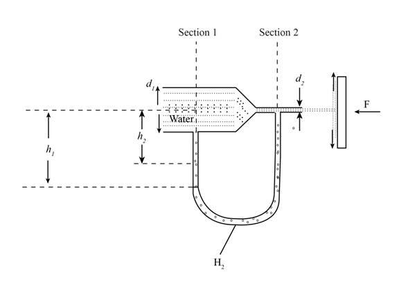
Figure (1)
Write the expression for the force with which the jet strikes a plate.
Here, the jet force on the plate is
Write the expression for cross section area in terms of nozzle diameter for section (1).
Write the expression for cross section area in terms of nozzle diameter for section (2).
Here, the diameter of the nozzle at section (1) is
Write the expression for momentum equation at section (1) and section (2).
Here, the cross-section area of the nozzle at section (1) is
Calculation:
Substitute
Substitute
Substitute
Thus, the velocity at section (2) is
Substitute
Conclusion:
Thus, the velocity at section (1) is
Thus, the velocity at section (2) is
(b)
The mercury manometer reading.
Answer to Problem 3.114P
The mercury manometer reading is
Explanation of Solution
Concept Used:
Write the expression for Bernoulli equation at section (1) and section (2).
Here, pressure at section (1) is
Write the expression for continuity equation.
Here, height of lower mercury level from the axis of the nozzle is
Calculation:
Substitute
Substitute
Conclusion:
Thus, the mercury manometer reading is
Want to see more full solutions like this?
Chapter 3 Solutions
Fluid Mechanics


- This is an old exam review problem. Please helparrow_forward3. The volumetric flow rate of air through a duct transition of the type shown in Table 12-9b (rectangular with two parallel sides) is 2 m3/s. The duct before the transition issquare, with a height of 50 cm. The expansion ratio across the transition is 4 (i.e., theduct area after the transition is 4 times greater than the duct area before the transition).a) Determine the pressure loss (in Pa) across the transition if the exit from the duct isabrupt (i.e., the diverging angle of the transition is 180º).b) Determine the percentage reduction in pressure loss for a transition diverging angleof 20º compared to the one in part (a).c) The head HVAC engineer requires the pressure loss across the transition to bereduced to less than 50% of the pressure loss for an abrupt exit (i.e., the case in part(a)), and suggests a transition diverging angle of 45º. Will this new diverging angleachieve the required reduction in pressure loss? Justify your answer.d) For a transition diverging angle of 90º,…arrow_forwardThe wheel shown is made of 2 rings and 8 rods. The otter ring weighs 100 lbs, the inner ring weighs 15 lbs,and each of the rods weighs 20 lbs. Find the moment of inertia of the wheel about an axis that comes directlyout of the page through point A.arrow_forward
- Mini project You are an engineer working for a power systems company responsible for ensuring grid stability. Your team has recently observed low-frequency oscillations in the system following disturbances such as load changes, faults, and switching operations. These oscillations have led to voltage instability, frequency deviations, and, in severe cases, system blackouts. A task force has been formed to address this issue, and you have been assigned a critical role in developing a damping control strategy. Your objective is to analyze system performance, propose engineering solutions, and compare the effects of different damping approaches. Answer the following questions 1. Identify the Engineering Problem: - What is the fundamental issue affecting power grid stability? - How do low-frequency oscillations impact the system's reliability? - What parameters indicate system instability? 2. Assess the Current Status Using Equations and Calculations: - Given the characteristic roots of the…arrow_forwardH.W 4: The beam shown below is subjected to the distributed loading of w=120 kN/m. Determine the principal stresses in the beam at point P, which lies at the top of the web. Neglect the size of the fillets and stress concentrations at this point. I=67.4×10⁻⁶ m4. 15 mm w=120 kN/m B 0.3 m 2 200 mm A 10 rim 15 mm 175 mmarrow_forwardA 3 m x 5 m section of wall of the cold room is not insulated, and the temperature at the outer surface of this section is measured to be 7°C. The temperature of the outside room is 30°C, and the combined convection and radiation heat transfer coefficient at the surface of the outer wall is 10 W/m2°C. It is proposed to insulate this section of the furnace wall with glass wool insulation (k = 0.038 W/m°C) in order to reduce the heat transfer by 90%. Assuming the outer surface temperature of the cold room wall section still remains at about 7°C, determine the thickness of the insulation that needs to be used.arrow_forward
- Q1/ For what value of x do the power series converge: ∞ Σ(-1)-1 n=1 x2n-1 2n-1 =x x3 3 5 Q2/ Find the Interval of convergence and Radius of convergence of the series : Σ n=1 n 3n+1 (x)" الممسوحة ضوئيا بـ CS CamScannerarrow_forwardThis refrigeration cycle uses R-134a as the working fluid and, for now, assume that it operates on an ideal vapour-compression refrigeration cycle between 0.11 and 1.0 MPa. If the mass flow rate of the refrigerant is 0.075 kg/s, determine What is the rate of heat removal from the refrigerated space? What is the power input to the compressor? What is the rate of heat rejection to the environment? What is the COP of this ideal process? Based on this analysis, what is the cost of electricity to operate the cold room for 1 year? Comment on why this differs to the value above Further data was collected which determined that the working fluid: enters the compressor at 0.11 MPa and -22°C leaves the compressor at 1.0 MPa and 60°C is cooled in the condenser to 0.9 MPa and 20°C is throttled to 0.12 MPa Disregarding any heat transfer or pressure losses in the pipes: What is the rate of heat removal from the refrigerated space? What is the power input to the compressor?…arrow_forward1 The refrigeration capacity of the cold room you are considering is 10 kW. It operates for 24 h/d, 360 days of the year. The average temperature outside the cold room is 30°C and the temperature of the air inside the cold room should be 5°C. What is the maximum coefficient of performance for this refrigeration cycle? What is the minimum work required? and If the price of electricity is 0.008 cents per kJ, what is the minimum cost of electricity to run the cold room for 1 year?arrow_forward
 Elements Of ElectromagneticsMechanical EngineeringISBN:9780190698614Author:Sadiku, Matthew N. O.Publisher:Oxford University Press
 Mechanics of Materials (10th Edition)Mechanical EngineeringISBN:9780134319650Author:Russell C. HibbelerPublisher:PEARSON
 Thermodynamics: An Engineering ApproachMechanical EngineeringISBN:9781259822674Author:Yunus A. Cengel Dr., Michael A. BolesPublisher:McGraw-Hill Education
 Control Systems EngineeringMechanical EngineeringISBN:9781118170519Author:Norman S. NisePublisher:WILEY
 Mechanics of Materials (MindTap Course List)Mechanical EngineeringISBN:9781337093347Author:Barry J. Goodno, James M. GerePublisher:Cengage Learning
 Engineering Mechanics: StaticsMechanical EngineeringISBN:9781118807330Author:James L. Meriam, L. G. Kraige, J. N. BoltonPublisher:WILEY