
Videos
The exit velocity of siphon tube with friction head losses.
The volume flow rate of the siphon tube with friction head losses.
The variation between the exit velocity and volume flow rate with and without friction head losses.
Answer to Problem 3.132P
The exit velocity of siphon tube with friction head losses
The volume flow rate of the siphon tube with friction losses head
The velocity and volume flow rate through the siphon tube is more if there is no head loss in the tube.
Explanation of Solution
Given information:
The diameter of the tube is
The Figure-(1) show different height at different sections.
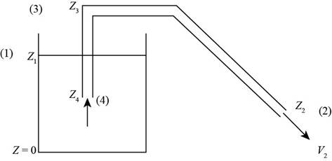
Figure-(1)
Here, the section (1) is for the top of the water level in the left region, the section (2) is at the exit of the siphon tube
Write the expression for the Bernoulli’s equation between the section (1) and section (2) of the given system.
Here, the pressure at section (1) is
Since the fluid at section (1) is stationary, so the velocity at the sections (1) is zero.
Since the pressure at the section (1) and section (2) is atmospheric, so the difference between the pressures is zero.
Write the expression for friction head loss in the siphon tube.
Here, the friction head loss in the siphon tube is
Substitute
Here, the exit velocity at section (2) with friction head losses is
Substitute
Here, the exit velocity at section (2) without friction head losses is
Write the expression for the flow rate at section (2) with friction losses.
Here, the flow rate is
Write the expression for the flow rate at section (2) without friction head losses.
Here, the flow rate is
Calculation:
Substitute
Substitute
Here diameter of the siphon tube is
Substitute
Substitute
Here diameter of the siphon tube is
Conclusion:
The exit velocity of siphon tube with friction head losses
The volume flow rate of the siphon tube with friction losses head
The velocity and volume flow rate through the siphon tube is more if there is no head loss in the tube.
Want to see more full solutions like this?
Chapter 3 Solutions
Fluid Mechanics


- What is quality? Does it have any meaning in the superheated vapour region? What is the difference between saturated vapor and superheated vapour? What is the difference between saturated liquid and compressed liquid? What is the difference between the critical point and the triple point?arrow_forwardHomework#5arrow_forwardDescribe the principle operation of PEMFC, and role of membrane electrode assembly (MEA).arrow_forward
- Homework#5arrow_forwardUsing graphical methods, draw the pressure angle at the position shown in (a) and (b). e |------- R = Cam Base Radius e = Follower Offset ẞ₁ = Section Duration 1 B₁ = Section Duration 2 ẞ₂ = Section Duration 3 В2 B₁ Follower Position ww R ẞ3 (a) Reference Radial (b)arrow_forwardThe figure below illustrates a graph that has a variable load torque and constant drive torque. Each cycle lasts three revolutions (6л radians). Torque (N-m) 600 550 400 1 200 TD= 225 N-m 2 + -T₁ 3 4 1 + 0 In addition, the rotation speed is @o steady-state conditions, determine 1. the average power required, 2πT 4π 5πT 6п Ꮎ = 180° rpm = 18.85 rad/sec, Imachine 125 kg-m². Assuming 2. the maximum and minimum rotational speeds throughout a cycle, 3. the mass of a 0.6-meter-diameter solid disc flywheel to produce Cs = 0.025.arrow_forward
- An elastic cord is stretched between 2 points A and B located 2y = 0.8 m apart in the horizontal plane. When stretched directly between A and B, the tension is P₂ = 40 N. The cord is then stretched as shown until its midpoint C has moved through x = 0.3 m to C', and a force of F = 240 N is required to hold the cord at C'. A pellet (m = 0.1 kg) is placed at C' and the cord is released. Find the speed of the pellet as it passes through C.arrow_forwardA 6305 ball bearing is subjected to a steady 5000-N radial load and a 2000-N thrust load and uses a very clean lubricant throughout its life. If the inner race angular velocity is 500rpm find (a) The equivalent radial load (b) The L10 life (c) The L50 lifearrow_forwardSlove this the question plearrow_forward
- Determine the Mean Effective Pressure (MEP) in [bar] for a 4-cylinder, 2-Stroke engine with a bore of 85.7 mm, and a stroke of 65.8 mm, that produces 85 hP at 5000 rpm. (Hint: Be careful with units). Note: 1 hP = 0.7457 kW; 100 kPa = 1 bararrow_forwardIbraheem Super Q3: A boiler as shown in the figure below is producing 2 kg/s saturated steam at 240C. The water enters the boiler at 24C. The boiler efficiency is 80%. Patm=1.05 bar .Determine: (10 Marks) 1- The inlet pressure of the turbine. 2- If a gauge pressure connected to the outlet pipe, what is the reading of this gauge? 3- Calculate the required diesel in [kg/s]. Assume the calorific value of the diesel is 45000 kJ/kgf 4- Calculate the equivalent evaporation of the boiler 5- Keeping the same inlet conditions and fuel consumption, determine the turbine efficiency if the produced steam was saturated at 300C. Steam Cut Hot Gasses Out Ts=240C Boiler FURNACE A Water In C 24 Examiner Head of Department Ahmad. A. M. Alsak laniarrow_forward##2# Superheated steam powers a steam turbine for the production of electrical energy. The steam expands in the turbine and at an intermediate expansion pressure (0.1 Mpa) a fraction is extracted for a regeneration process in a surface regenerator. The turbine has an isentropic efficiency of 90% Design the simplified power plant schematic Analyze it on the basis of the attached figure Determine the power generated and the thermal efficiency of the plant ### Dados in the attached imagesarrow_forward
 Elements Of ElectromagneticsMechanical EngineeringISBN:9780190698614Author:Sadiku, Matthew N. O.Publisher:Oxford University Press
 Mechanics of Materials (10th Edition)Mechanical EngineeringISBN:9780134319650Author:Russell C. HibbelerPublisher:PEARSON
 Thermodynamics: An Engineering ApproachMechanical EngineeringISBN:9781259822674Author:Yunus A. Cengel Dr., Michael A. BolesPublisher:McGraw-Hill Education
 Control Systems EngineeringMechanical EngineeringISBN:9781118170519Author:Norman S. NisePublisher:WILEY
 Mechanics of Materials (MindTap Course List)Mechanical EngineeringISBN:9781337093347Author:Barry J. Goodno, James M. GerePublisher:Cengage Learning
 Engineering Mechanics: StaticsMechanical EngineeringISBN:9781118807330Author:James L. Meriam, L. G. Kraige, J. N. BoltonPublisher:WILEY