
Concept explainers
Videos
(a)
The flow rate.
Answer to Problem 3.181P
The flow rate is
Explanation of Solution
Given information:
There is linear variation between the head and the flow rate.
The Figure-(1) shows the linear variation of the head with the flow rate.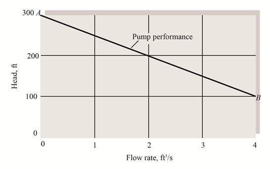
Figure-(1)
Here, the point on the graph is
Write the coordinates of the first point on the graph.
Write the coordinates of the second point on the graph.
Write the expression for the equation of straight line of the graph.
Here, the pump head is
Write the expression for the Bernoulli’s equation between the inlet and outlet of the pump.
Here, the pressure at inlet is
Write the expression for the head loss.
Here, the average velocity is
Substitute in
Write the expression for the flow rate.
Here, the area is
Write the expression for the area.
Here, the diameter is
Substitute
Substitute
Calculation:
Substitute
Since the pressure at the inlet and outlet are same so,
Since the diameter of the pipe is constant, so the velocity at section (1) and section (2) is same.
Substitute
Substitute
Substitute
Convert flow rate into
Conclusion:
The flow rate is
(b)
The horsepower required to drive the pump.
Answer to Problem 3.181P
The horsepower required to drive the pump is
Explanation of Solution
Given information:
The efficiency of the pump is
Write the expression for the power.
Here, the power is
Substitute
Calculation:
Substitute
Conclusion:
The horsepower required to drive the pump is
Want to see more full solutions like this?
Chapter 3 Solutions
Fluid Mechanics


- USE MATLAB ONLY Turbomachienery . GIven: vx = 185 m/s, flow angle = 60 degrees, R = 0.5, U = 150 m/s, b2 = -a3, a2 = -b3 Find: velocity triangle , a. magnitude of abs vel leaving rotor (m/s) b. flow absolute angles (a1, a2, a3) 3. flow rel angles (b2, b3) d. specific work done e. use code to draw vel. diagram Use this code for plot % plots Velocity Tri. in Ch4 function plotveltri(al1,al2,al3,b2,b3) S1L = [0 1]; V1x = [0 0]; V1s = [0 1*tand(al3)]; S2L = [2 3]; V2x = [0 0]; V2s = [0 1*tand(al2)]; W2s = [0 1*tand(b2)]; U2x = [3 3]; U2y = [1*tand(b2) 1*tand(al2)]; S3L = [4 5]; V3x = [0 0]; V3r = [0 1*tand(al3)]; W3r = [0 1*tand(b3)]; U3x = [5 5]; U3y = [1*tand(b3) 1*tand(al3)]; plot(S1L,V1x,'k',S1L,V1s,'r',... S2L,V2x,'k',S2L,V2s,'r',S2L,W2s,'b',U2x,U2y,'g',... S3L,V3x,'k',S3L,V3r,'r',S3L,W3r,'b',U3x,U3y,'g',...... 'LineWidth',2,'MarkerSize',10),... axis([-1 6 -4 4]), ... title('Velocity Triangle'), ... xlabel('x'),ylarrow_forwardThe wall of a furnace has a thickness of 5 cm and thermal conductivity of 0.7 W/m-°C. The inside surface is heated by convection with a hot gas at 402°C and a heat transfer coefficient of 37 W/m²-°C. The outside surface has an emissivity of 0.8 and is exposed to air at 27°C with a heat transfer coefficient of 20 W/m²-ºC. Assume that the furnace is inside a large room with walls, floor and ceiling at 27°C. Show the thermal circuit and determine the heat flux through the furnace wall. h₁ T₁ k -L T. sur ho Earrow_forwardTurbomachienery . GIven: vx = 185 m/s, flow angle = 60 degrees, R = 0.5, U = 150 m/s, b2 = -a3, a2 = -b3 Find: velocity triangle , a. magnitude of abs vel leaving rotor (m/s) b. flow absolute angles (a1, a2, a3) 3. flow rel angles (b2, b3) d. specific work done e. use code to draw vel. diagram Use this code for plot % plots Velocity Tri. in Ch4 function plotveltri(al1,al2,al3,b2,b3) S1L = [0 1]; V1x = [0 0]; V1s = [0 1*tand(al3)]; S2L = [2 3]; V2x = [0 0]; V2s = [0 1*tand(al2)]; W2s = [0 1*tand(b2)]; U2x = [3 3]; U2y = [1*tand(b2) 1*tand(al2)]; S3L = [4 5]; V3x = [0 0]; V3r = [0 1*tand(al3)]; W3r = [0 1*tand(b3)]; U3x = [5 5]; U3y = [1*tand(b3) 1*tand(al3)]; plot(S1L,V1x,'k',S1L,V1s,'r',... S2L,V2x,'k',S2L,V2s,'r',S2L,W2s,'b',U2x,U2y,'g',... S3L,V3x,'k',S3L,V3r,'r',S3L,W3r,'b',U3x,U3y,'g',...... 'LineWidth',2,'MarkerSize',10),... axis([-1 6 -4 4]), ... title('Velocity Triangle'), ... xlabel('x'),ylabel('y'), gridarrow_forward
- To save fuel during the heating season it is suggested that glass windows be covered at night with a 1.2 cm layer of polystyrene. Estimate the percent savings in energy and discuss the feasibility of this idea. Show the thermal circuit with and without the insulation panel. Consider a typical case of 0.2 cm thick window glass with inside and outside heat transfer coefficients of 6 and 32 W/m²-ºC. Lg←←Lp h T₁ T。 g kp insulation panelarrow_forwardA plate of thickness L and thermal conductivity k is exposed to a fluid at temperature T1 with a heat transfer coefficient h, on one side and T2 and h₂ on the other side. Determine the one-dimensional temperature distribution in the plate. Assume steady state and constant conductivity. L h h T%2 k Tx1 0xarrow_forwardDetermine the heater capacity needed to maintain the inside temperature of a laboratory chamber at 38°C when placed in a room at 21°C. The chamber is cubical with each side measuring 35 cm. The walls are 1.2 cm thick and are made of polystyrene. The inside and outside heat transfer coefficients are 5 and 22 W/m²-°C.arrow_forward
- (a) Refer to the above figure .What kind of controller is it ? (b) simplify the block diagramto derive the closed loop transfer function of the system. (C) What are the assumptions thatare needed to make to findthe controller gain ? What arethe value of Kp , Ti and Td ?arrow_forwardLonsider a regenerative gas turbine power plant with two stages of compression and two stages of expansion. The compressor pressure ratio of the compressor is 3. Air enters each stage of compressor at 290 K and esch stage of turbine at 1400 K. The regetierator has an effectiveness of 100%, Determine (a) The enthalpy at stage#2 in KJ/kg (b) The enthalpy at stage in KJ/kg" (c) The cathalpy at stager in KJ/kg* (d) The enthalpy at stage#10 in KJ/kg (c) The mass flow rate of air needed to develop a net power output of 50 MW *For all final answers please enter the integer part only, (ie 1234) and do not include the decimal part and the decimal point No rounding in your calculationarrow_forwardConsider a regenerative gas turbine power plant with two stages of compression and two stages of expansion. The compressor pressure ratio of the compressor is 3. Air enters each stage of compressor at 290 K and each stage of turbine at 1400 K. The regenerator has an effectiveness of 100%. Determine (a) The enthalpy at stage#2 in KJ/kg⭑ (b) The enthalpy at stage#6 in KJ/kg* (c) The enthalpy at stage#9 in KJ/kg (d) The enthalpy at stage#10 in KJ/kg (e)The mass flow rate of air needed to develop a net power output of 50 MW* *For all final answers please enter the integer part only, (ie 1234) and do not include the decimal part and the decimal point No rounding in your calculation. Compressor stage 1 Regenerator www HX ww 9 Combustor Reheat Intercooler ww Compressor stage 2 Turbine 1 combustor Turbine 2arrow_forward
- Design a proportional derivitivecontroller for a plant orsystemthat satisfies the following specifications : 1. is steady-state error is less than 2 % for a ramp input. 2.) Damping ratio (zeta) is greater than 0.7have determined the 3. Once youvalue of kp and kd, then plotthe response of the compensated(with controller) and uncompensated( without the controller, only the plantsystem using MATLAB.arrow_forwardExample 2 The particle has a mass of 0.5 kg and is confined to move along the smooth horizontal slot due to the rotation of the arm OA. Determine the force of the rod on the particle and the normal force of the slot on the particle when 0 = 30°. The rod is rotating with a constant angular velocity 2 rad/s. Assume the particle contacts only one side of the slot at any instant. B =2 rad/s 0.5 m 0.5(9.81)N r F 30° Narrow_forwardA gas turbine cycle has two stages of compression, with an intercooler between the stages. Air enters the first stage at 100 kPa, 300 K. The pressure efficiency of 82%. Air exits the intercooler at 330 K. Calculate the temperature at the exit of each compressor stage and the total specific work required.arrow_forward
 Elements Of ElectromagneticsMechanical EngineeringISBN:9780190698614Author:Sadiku, Matthew N. O.Publisher:Oxford University Press
 Mechanics of Materials (10th Edition)Mechanical EngineeringISBN:9780134319650Author:Russell C. HibbelerPublisher:PEARSON
 Thermodynamics: An Engineering ApproachMechanical EngineeringISBN:9781259822674Author:Yunus A. Cengel Dr., Michael A. BolesPublisher:McGraw-Hill Education
 Control Systems EngineeringMechanical EngineeringISBN:9781118170519Author:Norman S. NisePublisher:WILEY
 Mechanics of Materials (MindTap Course List)Mechanical EngineeringISBN:9781337093347Author:Barry J. Goodno, James M. GerePublisher:Cengage Learning
 Engineering Mechanics: StaticsMechanical EngineeringISBN:9781118807330Author:James L. Meriam, L. G. Kraige, J. N. BoltonPublisher:WILEY