
EBK PRINCIPLES OF ELECTRIC CIRCUITS
10th Edition
ISBN: 9780134880068
Author: Buchla
Publisher: VST
expand_more
expand_more
format_list_bulleted
Concept explainers
Videos
Textbook Question
Chapter 3, Problem 16RP
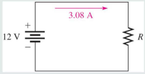
In the circuit of Figure 3-13, how much resistance is needed to draw 3.08 A of current from the battery?
FIGURE 3-13
Expert Solution & Answer
Want to see the full answer?
Check out a sample textbook solution
Students have asked these similar questions
Design a full-wave rectifier power supply using a 9.52:1 transformer. Assume that the outlet is120 V rms @ 60 Hz. Further assume that the diode turn-on voltage V D(on) is 0.7 V. Pick the valueof CL such that vo has a maximum ripple of 1 V p-p . Solve for the average value of vo = Vo (notethat this may be greater than 12 V) and iD(ave) = ID.
Light-emitting diodes (LEDs) are diodes made with III-V compound semiconductor materials such as aluminum gallium arsenide (AlGaAs), aluminum indium gallium phosphide (AlInGaP) or indium gallium nitride (InGaN), instead of silicon. The LEDs emit light when the device is operated under forward bias. LEDs of different colors have different turn-on voltages VD(on). For example:
VD(on) :
Red: ~ 1.6 V
Yellow: ~ 1.7 V
Green: ~ 1.8 V
Blue: ~ 2.8 V
White: ~ 3.8 V
(a) Model these five LEDs with a simplified piecewise linear model
(b) A rule of thumb is that it takes about 1 mA of current to “light” an LED while ~ 10 mA is needed for it to appear bright. Use the piecewise linear model for the LEDs, for the over-voltage indicator circuit to the right, find the values of Vin which will cause D1 or D2 to light (i.e. when ID1 or ID2 exceeds 1 mA).
Consider a fixed and updated instrumentation amplifier (where two resistors are lumped into one
resistor), analyze the circuit if a common voltage source (VICM) is connected to two inputs.
A₁
R₂
+
R₁
R₂,
RA
www
www
R₁
R₁
www
A3
X
R₁
R₂
www
www
R₁₂
+
Vo
RA
A2
V2 O-
+
R₂
12
R₁
Chapter 3 Solutions
EBK PRINCIPLES OF ELECTRIC CIRCUITS
Ch. 3 - If the current drops to 10 mA under the same...Ch. 3 - If the sense resistor develops 0.8 V across it,...Ch. 3 - Calculate the current in Figure 3-71 if R is...Ch. 3 - What is the current in mA produced by 1 kV across...Ch. 3 - How much current is there through a 6.8 M resistor...Ch. 3 - In Figure 3-10, how much voltage is required to...Ch. 3 - lf there are 3.2 A through a 47 resistor, what is...Ch. 3 - If there are 450 A through a 3.9 M resistor, what...Ch. 3 - In the circuit of Figure 3-13, how much resistance...Ch. 3 - If one of the grid wires opens, the current drops...
Ch. 3 - If the resistor is changed in Figure 3-14 so that...Ch. 3 - If the total resistance of a circuit increases and...Ch. 3 - Ohms law for finding resistance is R = I/V.Ch. 3 - When milliamps and kilohms are multiplied...Ch. 3 - If a 10 k resistor is connected to a 10 V source,...Ch. 3 - The current in a fixed resistor is directly...Ch. 3 - Ohms law for finding current is I = V/R.Ch. 3 - When microamps and megohms are multiplied, the...Ch. 3 - When voltage is constant, current is inversely...Ch. 3 - Ohms law for finding voltage is V = I/R.Ch. 3 - When I is plotted as a function of V for a fixed...Ch. 3 - Ohms law states that 1. current equals voltage...Ch. 3 - When the voltage across a resistor is doubled, the...Ch. 3 - When 10 V are applied across a 20 resistor, the...Ch. 3 - When there are 10 mA of current through 1.0 k...Ch. 3 - If 20 V are applied across a resistor and there...Ch. 3 - A current of 250 A through a 4.7 k resistor...Ch. 3 - A resistance of 2.2 M is connected across a 1 kV...Ch. 3 - How much resistance is required to limit the...Ch. 3 - An electric heater draws 2.5 A from a 110 V...Ch. 3 - The current through a flashlight bulb is 20 mA and...Ch. 3 - If the current through a fixed resistor goes from...Ch. 3 - If the voltage across a fixed resistor goes from...Ch. 3 - A variable resistor has 5 V across it. If you...Ch. 3 - If the voltage across a resistor increases from 5...Ch. 3 - If larger voltages are applied and results are...Ch. 3 - If the IV curve for a larger value resistor is...Ch. 3 - If the voltmeter reading changes to 175 V, the...Ch. 3 - If is changed to a larger value and the voltmeter...Ch. 3 - If the resistor is removed from the circuit...Ch. 3 - If the resistor is removed from the circuit...Ch. 3 - If the rheostat is adjusted to increase the...Ch. 3 - If the rheostat is adjusted to increase the...Ch. 3 - If the fuse opens, the voltage across the heating...Ch. 3 - If the source voltage increases, the voltage...Ch. 3 - If the fuse is changed to one with a higher...Ch. 3 - If the lamp burns out (opens), the current a....Ch. 3 - If the lamp burns out, the voltage across it a....Ch. 3 - In a circuit consisting of a voltage source and a...Ch. 3 - State the formula used to find I when the values...Ch. 3 - State the formula used to find V when the values...Ch. 3 - State the formula used to find R when the values...Ch. 3 - A variable voltage source is connected to the...Ch. 3 - In a certain circuit, I = 5 mA when V = 1 V....Ch. 3 - Figure 322 is a graph of current versus voltage...Ch. 3 - Plot the currentvoltage relationship for a...Ch. 3 - Plot the currentvoltage relationship for a...Ch. 3 - Determine the current in each circuit in Figure...Ch. 3 - You are measuring the current in a circuit that is...Ch. 3 - (a) If you wish to increase the amount of current...Ch. 3 - Plot a graph of current versus voltage for voltage...Ch. 3 - Does the graph in Problem 13 indicate a linear...Ch. 3 - Figure 3-24 shows an IV curve for a certain light...Ch. 3 - For the bulb graphed in Figure 3-24, what is the...Ch. 3 - Determine the current in each case: a. V = 5 V, R...Ch. 3 - Determine the current in each case: a. V = 9 V, R...Ch. 3 - Assume 200 mV is across a 330 m current sensing...Ch. 3 - A certain resistor has the following color code:...Ch. 3 - A 4-band resistor is connected across the...Ch. 3 - A 5-band resistor is connected across a 12 V...Ch. 3 - If the voltage in Problem 22 is doubled, will a...Ch. 3 - A certain rear window defroster has a resistance...Ch. 3 - If the voltage of the battery in problem 24 drops...Ch. 3 - The potentiometer connected as a rheostat in...Ch. 3 - A 270 current-limiting resistor has a voltage of...Ch. 3 - A small solar cell is connected to a 27 k...Ch. 3 - Calculate the voltage for each value of I and R:...Ch. 3 - Calculate the voltage for each value of I and R:...Ch. 3 - Three amperes of current are measured through a 27...Ch. 3 - Assign a voltage value to each source in the...Ch. 3 - A 6 V source is connected to a 100 resistor by...Ch. 3 - Calculate the resistance of a rheostat for each...Ch. 3 - Calculate the resistance of a rheostat for each...Ch. 3 - Six volts is applied across a resistor. A current...Ch. 3 - The filament of a lamp in the circuit of Figure...Ch. 3 - A certain electrical device has an unknown...Ch. 3 - By varying the rheostat (variable resistor) in the...Ch. 3 - In the light circuit of Figure 329, identify the...Ch. 3 - Assume you have a 32-light string and one of the...
Knowledge Booster


Learn more about
Need a deep-dive on the concept behind this application? Look no further. Learn more about this topic, electrical-engineering and related others by exploring similar questions and additional content below.Similar questions
- Show that the input impedance of a lossy transmission line of length L connected to a load impedance of Z is given by Z₁Cosh(yL) + ZoSinh(yL) Zin = Zo ZoCosh(YL) + Z₁Sihh(YL) ex Where Cosh(x) = and Sinh(x) = are the hyperbolic cosine and sine, respectively. 2 2arrow_forwardA sinusoidal source of V = 10 and Z = 50 - j40 is connected to a 60 lossless transmission line of length 100 m with ẞ = 0.25. What is the Thevenin's equivalent of this system seen looking into the load end of the transmission line?arrow_forward2. On a distortionless transmission line, the voltage wave is given by v(L,t) = 110e0.005L Cos(10³t + 2L) +55e-0.005L Cos(108t-2L) where L is the length of the transmission line as measured from the load. If Z = 30002, find a,ẞ, vp, and Zo.arrow_forward
- A 50 transmission line is to be connected to a 72 load through a 1/4 quarter wave matching transformer. (a) What must be the characteristic impedance of the transmission line that is used to form the quarter wave transformer? (b) If the frequency of operation is 7 MHz and the phase velocity through the quarter wave section is 2c/3, what is the length of the quarter wave section? You may assume the transmission line forming the quarter wave section is lossless.arrow_forwardWhat is the SWR on a transmission line if the forward power arriving at the load is 5W but only 4.6W is dissipated by the load?arrow_forwardPlease do not send the AI solution as it is full of errors. Solve the question yourself, please. Q- If you have a unipolar winding stepper motor, draw the driver and the control circuit. In subject (A stepper motor driver circuit and direction control using Arduino microcontroller)arrow_forward
- 1- Draw the complete circuit diagram that illustrates the experiment concept as in figure 5 by showing the pins number. Show the following in your plot (Arduino board, steppermotor coils and the driver circuit). Note: The drawing should be on paper and not with artificial intelligence, please.arrow_forwardIn the circuit shown, find the following: 1) The current Ix. 2) The average power dissipated in the capacitor. 3) The total average power dissipated in the two resistors. 4) The average power of the independent voltage source and specify whether it is supplied or absorbed. 5) The total impedance seen from the terminals of the independent voltage source (Z=V/I). 20 -201 12/00V(+ 21 www 202arrow_forward2- If you have a unipolar winding stepper motor, draw the driver and the control circuit. Note: The drawing is on paper.arrow_forward
- Given the following reaction system, where Xo is the input, i.e u(t) = k₁ × Xo: $Xo -> x1; k1*Xo x2; k2*x1 x1 2 x2 ->%; k3*x2^2 x2 ->; k4*x2 Xo 1; k1 = 0.4 k2 4.5; k3 = 0.75 k4= 0.2 a) Build the model in Tellurium and run a simulation. Compute the Jacobian at steady state using the method getFull Jacobian(). Make sure you are at steady state! b) Write out the values for n and p c) Write out the differential equations. d) Write out the state space representation in terms of the rate constants etc. e) Compute the values in the Jacobian matrix from d) by substituting the values of the rate constants etc and any data you need from the simulation. f) Confirm that the Jacobian you get in e) is the same as the one computed from the simulation in a). g) Is the system stable or not? If you find an eigenvalue of zero, that means the system is marginally stable. You can get the eigenvalues using the tellurium method r.getFullEigenvalues()arrow_forwardSolve by Pen and Paper not using chatgpt or AIarrow_forwardYou just got a job at Shin-Etsu Chemical growing Si crystals with different dopants. Howmuch Ga needs to be added to 800 kg of Si melt to achieve a 5-10 Ω.cm (measured at midheight) Si CZ crystal with the following characteristics: height: 7 ft, width: 12 inchesdiameter. Assume, angular rotation 10 RPM, melt viscosity 0.1 poise, pull velocity 2mm/min.a. Generate a plot of the doping distribution throughout the length of the crystal (CGa vs. fs ).b. If a second crystal were to be pulled out of the melt without replenishment of silicon nordopant what would be the average resistivity of this crystal (or resistivity at mid height)arrow_forward
arrow_back_ios
SEE MORE QUESTIONS
arrow_forward_ios
Recommended textbooks for you
 Electricity for Refrigeration, Heating, and Air C...Mechanical EngineeringISBN:9781337399128Author:Russell E. SmithPublisher:Cengage Learning
Electricity for Refrigeration, Heating, and Air C...
Mechanical Engineering
ISBN:9781337399128
Author:Russell E. Smith
Publisher:Cengage Learning
Z Parameters - Impedance Parameters; Author: Electrical Engineering Authority;https://www.youtube.com/watch?v=qoD4AoNmySA;License: Standard Youtube License