
EBK PRINCIPLES OF ELECTRIC CIRCUITS
10th Edition
ISBN: 9780134880068
Author: Buchla
Publisher: VST
expand_more
expand_more
format_list_bulleted
Concept explainers
Videos
Textbook Question
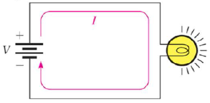
Chapter 3, Problem 17CDQ
If the lamp burns out, the voltage across it
- a. increases
- b. decreases
- c. stays the same
Figure 3–27
Expert Solution & Answer
Want to see the full answer?
Check out a sample textbook solution
Students have asked these similar questions
ntotn
In Fig.35 resistive loads, 1, 2, and 3, respectively, absorb 1200 W, 2400 W, and 3600 W. Calculate the current:
a. In lines A and B.
b. In the neutral conductors.
c. In the HV line.
+
-ww
I
2
12V
2
Determine I, I,, I₂ and V₁
1 _< +
www
5 12
16
6
5
www
Chapter 3 Solutions
EBK PRINCIPLES OF ELECTRIC CIRCUITS
Ch. 3 - If the current drops to 10 mA under the same...Ch. 3 - If the sense resistor develops 0.8 V across it,...Ch. 3 - Calculate the current in Figure 3-71 if R is...Ch. 3 - What is the current in mA produced by 1 kV across...Ch. 3 - How much current is there through a 6.8 M resistor...Ch. 3 - In Figure 3-10, how much voltage is required to...Ch. 3 - lf there are 3.2 A through a 47 resistor, what is...Ch. 3 - If there are 450 A through a 3.9 M resistor, what...Ch. 3 - In the circuit of Figure 3-13, how much resistance...Ch. 3 - If one of the grid wires opens, the current drops...
Ch. 3 - If the resistor is changed in Figure 3-14 so that...Ch. 3 - If the total resistance of a circuit increases and...Ch. 3 - Ohms law for finding resistance is R = I/V.Ch. 3 - When milliamps and kilohms are multiplied...Ch. 3 - If a 10 k resistor is connected to a 10 V source,...Ch. 3 - The current in a fixed resistor is directly...Ch. 3 - Ohms law for finding current is I = V/R.Ch. 3 - When microamps and megohms are multiplied, the...Ch. 3 - When voltage is constant, current is inversely...Ch. 3 - Ohms law for finding voltage is V = I/R.Ch. 3 - When I is plotted as a function of V for a fixed...Ch. 3 - Ohms law states that 1. current equals voltage...Ch. 3 - When the voltage across a resistor is doubled, the...Ch. 3 - When 10 V are applied across a 20 resistor, the...Ch. 3 - When there are 10 mA of current through 1.0 k...Ch. 3 - If 20 V are applied across a resistor and there...Ch. 3 - A current of 250 A through a 4.7 k resistor...Ch. 3 - A resistance of 2.2 M is connected across a 1 kV...Ch. 3 - How much resistance is required to limit the...Ch. 3 - An electric heater draws 2.5 A from a 110 V...Ch. 3 - The current through a flashlight bulb is 20 mA and...Ch. 3 - If the current through a fixed resistor goes from...Ch. 3 - If the voltage across a fixed resistor goes from...Ch. 3 - A variable resistor has 5 V across it. If you...Ch. 3 - If the voltage across a resistor increases from 5...Ch. 3 - If larger voltages are applied and results are...Ch. 3 - If the IV curve for a larger value resistor is...Ch. 3 - If the voltmeter reading changes to 175 V, the...Ch. 3 - If is changed to a larger value and the voltmeter...Ch. 3 - If the resistor is removed from the circuit...Ch. 3 - If the resistor is removed from the circuit...Ch. 3 - If the rheostat is adjusted to increase the...Ch. 3 - If the rheostat is adjusted to increase the...Ch. 3 - If the fuse opens, the voltage across the heating...Ch. 3 - If the source voltage increases, the voltage...Ch. 3 - If the fuse is changed to one with a higher...Ch. 3 - If the lamp burns out (opens), the current a....Ch. 3 - If the lamp burns out, the voltage across it a....Ch. 3 - In a circuit consisting of a voltage source and a...Ch. 3 - State the formula used to find I when the values...Ch. 3 - State the formula used to find V when the values...Ch. 3 - State the formula used to find R when the values...Ch. 3 - A variable voltage source is connected to the...Ch. 3 - In a certain circuit, I = 5 mA when V = 1 V....Ch. 3 - Figure 322 is a graph of current versus voltage...Ch. 3 - Plot the currentvoltage relationship for a...Ch. 3 - Plot the currentvoltage relationship for a...Ch. 3 - Determine the current in each circuit in Figure...Ch. 3 - You are measuring the current in a circuit that is...Ch. 3 - (a) If you wish to increase the amount of current...Ch. 3 - Plot a graph of current versus voltage for voltage...Ch. 3 - Does the graph in Problem 13 indicate a linear...Ch. 3 - Figure 3-24 shows an IV curve for a certain light...Ch. 3 - For the bulb graphed in Figure 3-24, what is the...Ch. 3 - Determine the current in each case: a. V = 5 V, R...Ch. 3 - Determine the current in each case: a. V = 9 V, R...Ch. 3 - Assume 200 mV is across a 330 m current sensing...Ch. 3 - A certain resistor has the following color code:...Ch. 3 - A 4-band resistor is connected across the...Ch. 3 - A 5-band resistor is connected across a 12 V...Ch. 3 - If the voltage in Problem 22 is doubled, will a...Ch. 3 - A certain rear window defroster has a resistance...Ch. 3 - If the voltage of the battery in problem 24 drops...Ch. 3 - The potentiometer connected as a rheostat in...Ch. 3 - A 270 current-limiting resistor has a voltage of...Ch. 3 - A small solar cell is connected to a 27 k...Ch. 3 - Calculate the voltage for each value of I and R:...Ch. 3 - Calculate the voltage for each value of I and R:...Ch. 3 - Three amperes of current are measured through a 27...Ch. 3 - Assign a voltage value to each source in the...Ch. 3 - A 6 V source is connected to a 100 resistor by...Ch. 3 - Calculate the resistance of a rheostat for each...Ch. 3 - Calculate the resistance of a rheostat for each...Ch. 3 - Six volts is applied across a resistor. A current...Ch. 3 - The filament of a lamp in the circuit of Figure...Ch. 3 - A certain electrical device has an unknown...Ch. 3 - By varying the rheostat (variable resistor) in the...Ch. 3 - In the light circuit of Figure 329, identify the...Ch. 3 - Assume you have a 32-light string and one of the...
Additional Engineering Textbook Solutions
Find more solutions based on key concepts
This optional Google account security feature sends you a message with a code that you must enter, in addition ...
SURVEY OF OPERATING SYSTEMS
The solid steel shaft AC has a diameter of 25 mm and is supported by smooth bearings at D and E. It is coupled ...
Mechanics of Materials (10th Edition)
Assume a telephone signal travels through a cable at two-thirds the speed of light. How long does it take the s...
Electric Circuits. (11th Edition)
What output will the following lines of code display on the screen? cout "The works of Wolfgang\ninclude the f...
Starting Out with C++: Early Objects (9th Edition)
In Exercises 1 through 22, determine the output displayed in the text box or list box by the lines of code.
Introduction To Programming Using Visual Basic (11th Edition)
CONCEPT QUESTIONS
15.CQ3 The ball rolls without slipping on the fixed surface as shown. What is the direction ...
Vector Mechanics for Engineers: Statics and Dynamics
Knowledge Booster


Learn more about
Need a deep-dive on the concept behind this application? Look no further. Learn more about this topic, electrical-engineering and related others by exploring similar questions and additional content below.Similar questions
- Determine (a) the average and (b) rms values of the periodiccurrent waveform shown in Fig. P8.9arrow_forwardRepairs have to be carried out on HV cir- cuit breaker No. 6 shown in Fig. 26. If the three 220 kV lines must be kept in service, which disconnecting switches must be kept open?arrow_forwardFind the voltage v(t) for t>=0 show all steps and redraw circuit as necessary, the switch closes at t=0 and v(t) is the voltage over the 4ohm resistor as shown in the circuit.arrow_forward
- Find the voltage v(t) for t>=0 please redraw circuit as necessary and show all steps.arrow_forwardDetermine (a) the average and (b) rms values of the periodiccurrent waveform shown in Fig. P8.9arrow_forwardFind Eigenvalues and Eigenvectors for the following matrices: [5 -6 1 A = 1 1 0 3 0 1arrow_forward
- Use Gauss-Jordan Elimination method to solve the following system: 4x1+5x2 + x3 = 2 x1-2x2-3x3 = 7 3x1 x2 2x3 = 1. -arrow_forward3. As the audio frequency of Fig. 11-7 goes down, what components of Fig. 12-4 must be modified for normal operation? OD C₂ 100 HF R₁ 300 Re 300 ww 100A R 8 Voc Rz 10k reset output 3 R7 8 Voc 3 reset output Z discharge VR₁ 5k 2 trigger 2 trigger 7 discharge R 3 1k 5 control voltage threshold 6 5 control voltage 6 threshold GND Rs 2k C. C. 100 GND Uz LM555 1 Ce 0.01 U, LM555 0.01 8.01.4 PRO Fig. 11-7 Audio lutput Pulse width modulator R4 1k ww C7 Re 1k ww R7 100 VR 50k 10μ Ra R10 C₁. R1 3.9k 3.9k 0.14 100k TO w Rs 51 82 3 H 10 Carrier U₁ Ca Input A741 2.2 Us MC1496 PWM signal input R2 0.1100k Uz A741 41 Cs 1 Re 10k VR2 50k VR3 100k 14 12 C3. 3% + Ce 0.1 10μ 5 1A HH C +12V 0.1 O PWM Output C 0.02- R 100k +12 V Demodulated output 6 Ca 0.33 w R 10k R12 100k ww 31 о + 4A741 -12 V Fig. 12-4 PWM demodulator C 1500parrow_forwardDUC 1. In Fig. 12-4, what are the functions of the VR1 and VR2? 2. In Fig. 12-4, what is the function of the VR3? VR₁ 50k C₁ R1 0.1 100k Carrier Input U₁ A741 PWM signal input R41k www Re 1k w C7 ± 10μT R7 100 ww =L H C4 2.2 H W82 Rs 51 3 10 U3 MC1496 C2 R2 U2 A741 22 0.1 100k VR2 50k VR3 100kr 14 C3 10μ 1k 0.1 4 5 6 12 m Re 10k R9 R102 3.9k 3.9k HHI C10 0.1 -0 +12V C11 R 0.02 100k +12 V Demodulated output C R11 R12 A741 0.33 10k 100k -12 V Ca 1μ C12 1500p PRODUC Fig. 12-4 PWM demodulator PRODUCTSarrow_forward
- 10.37 Use mesh analysis to find currents I₁, I2, and I3 in the circuit of Fig. 10.82. ML 120-90° V 120 -30° V Figure 10.82 For Prob. 10.37. N N Z=80-135arrow_forward3. Find the phasor current I。 in the circuit shown below. Be aware of the direction markings. (15 pts) 1052 I 5057 ①520 Amps 2012 j5052arrow_forward10.93 Figure 10.135 shows a Colpitts oscillator. Show that the ed oscillation frequency is 1 fo= 2π √√LCT where CTC₁C2/(C₁ + C₂). Assume R; >>> R₁ + Rf ww Vo L m C₂ C₁ 5 Xci Figure 10.135 A Colpitts oscillator; for Prob. 10.93. (Hint: Set the imaginary part of the impedance in the feedback circuit equal to zero.)arrow_forward
arrow_back_ios
SEE MORE QUESTIONS
arrow_forward_ios
Recommended textbooks for you
 Electricity for Refrigeration, Heating, and Air C...Mechanical EngineeringISBN:9781337399128Author:Russell E. SmithPublisher:Cengage Learning
 Delmar's Standard Textbook Of ElectricityElectrical EngineeringISBN:9781337900348Author:Stephen L. HermanPublisher:Cengage Learning
Electricity for Refrigeration, Heating, and Air C...
Mechanical Engineering
ISBN:9781337399128
Author:Russell E. Smith
Publisher:Cengage Learning
Delmar's Standard Textbook Of Electricity
Electrical Engineering
ISBN:9781337900348
Author:Stephen L. Herman
Publisher:Cengage Learning
What is an electric furnace and how does it work?; Author: Fire & Ice Heating and Air Conditioning Inc;https://www.youtube.com/watch?v=wjAWecPGi0M;License: Standard Youtube License