a.
To calculate: Base current.
a.
Answer to Problem 53A
Base current =
Explanation of Solution
Given:
The following figure:
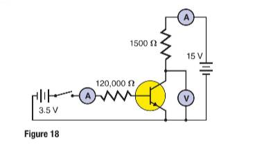
The switch shown in the figure is on.
Voltage drop across base-emitter junction =
Current gain from base-collector junction =
Formula used:
Current is given by,
Where y
Calculation:
Base current is calculated as:
Conclusion:
Base current =
b.
To calculate: Collector current.
b.
Answer to Problem 53A
Collector current =
Explanation of Solution
Given:
The following figure:

The switch shown in the figure is on.
Voltage drop across base-emitter junction =
Current gain from base-collector junction =
Formula used:
Current gain is given by,
Where
Calculation:
Collector current is calculated as:
Conclusion:
Collector current =
c.
To calculate: Voltmeter reading.
c.
Answer to Problem 53A
Voltmeter reading =
Explanation of Solution
Given:
The following figure:

The switch shown in the figure is on.
Voltage drop across base-emitter junction =
Current gain from base-collector junction =
Formula used:
Voltage is given by,
Where
The voltmeter reading is given by,
Calculation:
Voltage across
Voltmeter reading is calculated as,
Conclusion:
Voltmeter reading =
Chapter 29 Solutions
Glencoe Physics: Principles and Problems, Student Edition
Additional Science Textbook Solutions
Campbell Essential Biology (7th Edition)
Brock Biology of Microorganisms (15th Edition)
Campbell Biology (11th Edition)
Chemistry: An Introduction to General, Organic, and Biological Chemistry (13th Edition)
Cosmic Perspective Fundamentals
College Physics: A Strategic Approach (3rd Edition)

- Lab 8 Part 3 PHET Wave Interface simulation. I am having trouble with this part of the lab.arrow_forwardMick and Rick are twins born on Earth in the year 2175. Rick grows up to be an Earth-bound robotics technician while Mick becomes an intergalactic astronaut. Mick leaves the Earth on his first space mission in the year 2200 and travels, according to his clock, for 10 years at a speed of 0.75c. Unfortunately, at this point in his journey, the structure of his ship undergoes mechanical breakdown and the ship explodes. How old is Rick when his brother dies?arrow_forwardHi, I have canceled, why did you charge me again?arrow_forward
- You are standing a distance x = 1.75 m away from this mirror. The object you are looking at is y = 0.29 m from the mirror. The angle of incidence is θ = 30°. What is the exact distance from you to the image?arrow_forwardFor each of the actions depicted below, a magnet and/or metal loop moves with velocity v→ (v→ is constant and has the same magnitude in all parts). Determine whether a current is induced in the metal loop. If so, indicate the direction of the current in the loop, either clockwise or counterclockwise when seen from the right of the loop. The axis of the magnet is lined up with the center of the loop. For the action depicted in (Figure 5), indicate the direction of the induced current in the loop (clockwise, counterclockwise or zero, when seen from the right of the loop). I know that the current is clockwise, I just dont understand why. Please fully explain why it's clockwise, Thank youarrow_forwardA planar double pendulum consists of two point masses \[m_1 = 1.00~\mathrm{kg}, \qquad m_2 = 1.00~\mathrm{kg}\]connected by massless, rigid rods of lengths \[L_1 = 1.00~\mathrm{m}, \qquad L_2 = 1.20~\mathrm{m}.\]The upper rod is hinged to a fixed pivot; gravity acts vertically downward with\[g = 9.81~\mathrm{m\,s^{-2}}.\]Define the generalized coordinates \(\theta_1,\theta_2\) as the angles each rod makes with thedownward vertical (positive anticlockwise, measured in radians unless stated otherwise).At \(t=0\) the system is released from rest with \[\theta_1(0)=120^{\circ}, \qquad\theta_2(0)=-10^{\circ}, \qquad\dot{\theta}_1(0)=\dot{\theta}_2(0)=0 .\]Using the exact nonlinear equations of motion (no small-angle or planar-pendulumapproximations) and assuming the rods never stretch or slip, determine the angle\(\theta_2\) at the instant\[t = 10.0~\mathrm{s}.\]Give the result in degrees, in the interval \((-180^{\circ},180^{\circ}]\).arrow_forward
- What are the expected readings of the ammeter and voltmeter for the circuit in the figure below? (R = 5.60 Ω, ΔV = 6.30 V) ammeter I =arrow_forwardsimple diagram to illustrate the setup for each law- coulombs law and biot savart lawarrow_forwardA circular coil with 100 turns and a radius of 0.05 m is placed in a magnetic field that changes at auniform rate from 0.2 T to 0.8 T in 0.1 seconds. The plane of the coil is perpendicular to the field.• Calculate the induced electric field in the coil.• Calculate the current density in the coil given its conductivity σ.arrow_forward
 College PhysicsPhysicsISBN:9781305952300Author:Raymond A. Serway, Chris VuillePublisher:Cengage Learning
 University Physics (14th Edition)PhysicsISBN:9780133969290Author:Hugh D. Young, Roger A. FreedmanPublisher:PEARSON
 Introduction To Quantum MechanicsPhysicsISBN:9781107189638Author:Griffiths, David J., Schroeter, Darrell F.Publisher:Cambridge University Press
 Physics for Scientists and EngineersPhysicsISBN:9781337553278Author:Raymond A. Serway, John W. JewettPublisher:Cengage Learning
 Lecture- Tutorials for Introductory AstronomyPhysicsISBN:9780321820464Author:Edward E. Prather, Tim P. Slater, Jeff P. Adams, Gina BrissendenPublisher:Addison-Wesley
 College Physics: A Strategic Approach (4th Editio...PhysicsISBN:9780134609034Author:Randall D. Knight (Professor Emeritus), Brian Jones, Stuart FieldPublisher:PEARSON