
Statics and Mechanics of Materials (5th Edition)
5th Edition
ISBN: 9780134382593
Author: Russell C. Hibbeler
Publisher: PEARSON
expand_more
expand_more
format_list_bulleted
Videos
Textbook Question
Chapter 2.9, Problem 30FP
Determine the components of the force acting parallel and perpendicular to the axis of the pole.
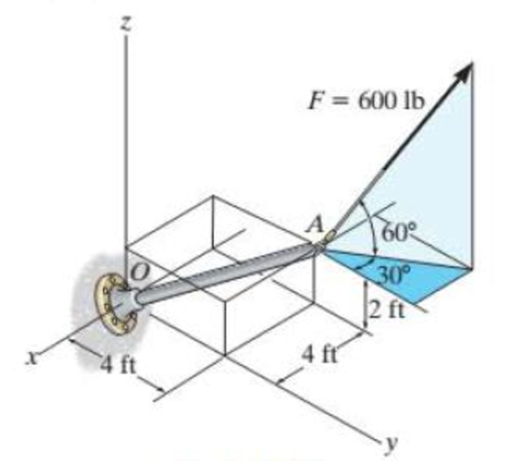
Prob. F2–30
Expert Solution & Answer
Want to see the full answer?
Check out a sample textbook solution
Students have asked these similar questions
=
The steel curved bar shown has rectangular cross-section with a radial height h = 6 mm and thickness b = 4mm. The
radius of the centroidal axis is R = 80 mm. A force P = 10 N is applied as shown. Assume the steel modulus of
207,000 MPa and G = 79.3(103) MPa, repectively.
elasticity and shear modulus E =
Find the vertical deflection at point B. Use Castigliano's method for a curved flexural member and since R/h > 10,
neglect the effect of shear and axial load, thereby assuming that deflection is due to merely the bending moment.
Note the inner and outer radii of the curves bar are:
r = 80 + ½ (6) = 83 mm, r₁ = 80 − ½ (6) = 77 mm
2
2
Sπ/2 sin² 0 d = √π/² cos² 0 d0 =
Π
0
4
大
C
R
B
P
The steel eyebolt shown in the figure is loaded with a force F = 75 lb. The eyebolt is formed from round wire of
diameter d = 0.25 in to a radius R₁ = 0.50 in in the eye and at the shank.
Estimate the stresses at the inner and outer surfaces at section A-A.
Notice at the section A-A:
r₁ = 0.5 in, ro
= 0.75 in
rc
=
0.5 + 0.125 = 0.625 in
Ri
200
F
FA
I have the fallowing question and solution from a reeds naval arc book. Im just confused as to where this answer came from and the formulas used. Wondering if i could have this answer/ solution broken down and explained in detail.
A ship of 7000 tonne displacement has a waterplane areaof 1500 m2. In passing from sea water into river water of1005 kg/m3 there is an increase in draught of 10 cm. Find the Idensity of the sea water.
picture of the "answer" is attached
Chapter 2 Solutions
Statics and Mechanics of Materials (5th Edition)
Ch. 2.3 - In each case, construct the parallelogram law to...Ch. 2.3 - In each case, show how to resolve the force F into...Ch. 2.3 - Determine the magnitude of the resultant force...Ch. 2.3 - Determine the magnitude of the resultant force....Ch. 2.3 - Determine the magnitude of the resultant force and...Ch. 2.3 - Resolve the 30-lb force into components along the...Ch. 2.3 - Resolve the force into components acting along...Ch. 2.3 - Prob. 6FPCh. 2.3 - If = 60 and F = 450 N, determine the magnitude of...Ch. 2.3 - If the magnitude of the resultant force is to be...
Ch. 2.3 - Determine the magnitude of the resultant force FR...Ch. 2.3 - Determine the magnitudes of the two components of...Ch. 2.3 - Solve Prob. 24 with F = 350 lb. 24. Determine the...Ch. 2.3 - Determine the magnitude of the resultant force FR...Ch. 2.3 - Resolve the force F1 into components acting along...Ch. 2.3 - Resolve the force F2 into components acting along...Ch. 2.3 - If the resultant force acting on the support is to...Ch. 2.3 - Determine the magnitude of the resultant force and...Ch. 2.3 - If = 60, determine the magnitude of the resultant...Ch. 2.3 - Determine the angle for connecting member A to...Ch. 2.3 - The force acting on the gear tooth is F = 20 lb....Ch. 2.3 - The component of force F acting along line aa is...Ch. 2.3 - Force F acts on the frame such that its component...Ch. 2.3 - Force F acts on the frame such that its component...Ch. 2.3 - If F1 = 30 lb and F2 = 40 lb, determine the angles...Ch. 2.3 - Determine the magnitude and direction of FA so...Ch. 2.3 - Determine the magnitude of the resultant force...Ch. 2.3 - Prob. 20PCh. 2.3 - If the resultant force of the two tugboats is 3...Ch. 2.3 - If FB = 3 kN and = 45, determine the magnitude of...Ch. 2.3 - If the resultant force of the two tugboats is...Ch. 2.4 - Resolve each force into its x and y components....Ch. 2.4 - F28. Determine the magnitude and direction of the...Ch. 2.4 - Prob. 9FPCh. 2.4 - Prob. 10FPCh. 2.4 - Prob. 11FPCh. 2.4 - Determine the magnitude of the resultant force and...Ch. 2.4 - Determine the magnitude of the resultant force and...Ch. 2.4 - Prob. 25PCh. 2.4 - Prob. 26PCh. 2.4 - Determine the magnitude of the resultant force and...Ch. 2.4 - Prob. 28PCh. 2.4 - Determine the magnitude of the resultant force...Ch. 2.4 - Prob. 30PCh. 2.4 - Prob. 31PCh. 2.4 - Prob. 32PCh. 2.4 - Determine the magnitude of the resultant force and...Ch. 2.4 - Prob. 34PCh. 2.4 - Prob. 35PCh. 2.4 - Determine the magnitude of the resultant force and...Ch. 2.4 - Determine the magnitude and direction of the...Ch. 2.6 - Sketch the following forces on the x, y, z...Ch. 2.6 - In each case, establish F as a Cartesian vector,...Ch. 2.6 - Show how to resolve each force into its x, y, z...Ch. 2.6 - Determine the coordinate direction angles of the...Ch. 2.6 - Prob. 14FPCh. 2.6 - Prob. 15FPCh. 2.6 - Prob. 16FPCh. 2.6 - Prob. 17FPCh. 2.6 - Determine the resultant force acting on the hook....Ch. 2.6 - The force F has a magnitude of 80 lb. Determine...Ch. 2.6 - The bolt is subjected to the force F, which has...Ch. 2.6 - Determine the magnitude and coordinate direction...Ch. 2.6 - Prob. 41PCh. 2.6 - Prob. 42PCh. 2.6 - Express each force in Cartesian vector form and...Ch. 2.6 - Prob. 44PCh. 2.6 - Determine the magnitude and coordinate direction...Ch. 2.6 - Determine the magnitude and coordinate direction...Ch. 2.6 - Prob. 47PCh. 2.6 - Determine the magnitude and coordinate direction...Ch. 2.6 - Prob. 49PCh. 2.6 - Prob. 50PCh. 2.6 - Prob. 51PCh. 2.6 - Determine the magnitude and coordinate direction...Ch. 2.6 - Prob. 53PCh. 2.6 - Prob. 54PCh. 2.6 - Determine the magnitude and coordinate direction...Ch. 2.8 - In each case, establish a position vector from...Ch. 2.8 - In each case, express F as a Cartesian vector. (a)...Ch. 2.8 - Prob. 19FPCh. 2.8 - Determine the length of the rod and the position...Ch. 2.8 - Prob. 21FPCh. 2.8 - Express the force as a Cartesian vector. Prob....Ch. 2.8 - Prob. 23FPCh. 2.8 - Prob. 24FPCh. 2.8 - Determine the length of the connecting rod AB by...Ch. 2.8 - Express force F as a Cartesian vector; then...Ch. 2.8 - Express each force as a Cartesian vector, and then...Ch. 2.8 - If F = {350i 250j 450k} N and cable AB is 9 m...Ch. 2.8 - The 8-m-long cable is anchored to the ground at A....Ch. 2.8 - The 8-m-long cable is anchored to the ground at A....Ch. 2.8 - Express each of the forces in Cartesian vector...Ch. 2.8 - If FB = 560 N and FC = 700 N, determine the...Ch. 2.8 - If FB = 700 N, and FC = 560 N, determine the...Ch. 2.8 - The plate is suspended using the three cables...Ch. 2.8 - Prob. 66PCh. 2.8 - Determine the magnitude and coordinate direction...Ch. 2.8 - Prob. 68PCh. 2.8 - The load at A creates a force of 60 lb in wire AB....Ch. 2.8 - Determine the magnitude and coordinate direction...Ch. 2.9 - In each case, set up the dot product to find the...Ch. 2.9 - In each case, set up the dot product to find the...Ch. 2.9 - Determine the angle between the force and the...Ch. 2.9 - Determine the angle between the force and the...Ch. 2.9 - Determine the angle between the force and the...Ch. 2.9 - Determine the projected component of the force...Ch. 2.9 - Find the magnitude of the projected component of...Ch. 2.9 - Determine the components of the force acting...Ch. 2.9 - Prob. 31FPCh. 2.9 - Prob. 71PCh. 2.9 - Determine the magnitudes of the components of F =...Ch. 2.9 - Determine the angle between BA and BC. Probs. 273Ch. 2.9 - Determine the magnitude of the projected component...Ch. 2.9 - Prob. 75PCh. 2.9 - Determine the magnitude of the projection of the...Ch. 2.9 - Determine the angle between the pole and the wire...Ch. 2.9 - Determine the magnitude of the projection of the...Ch. 2.9 - Determine the magnitude of the projected component...Ch. 2.9 - Prob. 80PCh. 2.9 - Determine the angle between the two cables. Prob....Ch. 2.9 - Determine the projected component of the force...Ch. 2.9 - Determine the angles and between the flag pole...Ch. 2.9 - Determine the magnitudes of the components of F...Ch. 2.9 - Prob. 85PCh. 2.9 - Determine the angle between the pipe segments BA...Ch. 2.9 - If the force F = 100 N lies in the plane DBEC,...Ch. 2.9 - Determine the magnitudes of the components of the...Ch. 2.9 - Determine the magnitudes of the projected...Ch. 2.9 - Determine the magnitude of the projected component...Ch. 2.9 - Two cables exert forces on the pipe. Determine the...Ch. 2.9 - Determine the angle between the two forces. Prob....Ch. 2 - Determine the magnitude of the resultant force FR...Ch. 2 - Resolve the force into components along the u and...Ch. 2 - Determine the magnitude of the resultant force...Ch. 2 - The cable exerts a force of 250 lb on the crane...Ch. 2 - The cable attached to the tractor at B exerts a...Ch. 2 - Express F1 and F2 as Cartesian vectors. Prob. R26Ch. 2 - Determine the angle between the edges of the...Ch. 2 - Determine the projection of the force F along the...
Knowledge Booster


Learn more about
Need a deep-dive on the concept behind this application? Look no further. Learn more about this topic, mechanical-engineering and related others by exploring similar questions and additional content below.Similar questions
- Problem A2 long steel tube has a rectangular cross-section with outer dimensions of 20 x 20 mm and a uniform wall thickness of 2. The tube is twisted along its length with torque, T. The tube material is 1045 CD steel with shear yield strength of S,, =315 MPa. Assume shear modulus, G = 79.3GPa. (a) Estimate the maximum torque that can be applied without yielding (b) Estimate the torque required to produce 5 degrees total angle of twist over the length of the tube. (c) What is the maximum torque that can be applied without yielding, if a solid rectangular shaft with dimensions of 20 x 20 is used? You may use the exact solution.arrow_forwardA simply supported beam is loaded as shown. Considering symmetry, the reactions at supports A and B are R₁ = R₂ = wa 2 Using the singularity method, determine the shear force V along the length of the beam as a function of distance x from the support A. A B Ir. 2a За W C R₁₂ x 2. Using the singularity method, determine the bending M along the length of the beam as a function of distance x, from the support A. 3. Using the singularity method, determine the beam slope and deflection along the length of the beam as a function of the distance x, from the support A. Assume the material modulus of elasticity, E and the moment of inertia of the beam cross-section, I are given.arrow_forwardA steel tube, 2 m long, has a rectangular cross-section with outer dimensions of 20 × 30 mm and a uniform wall thickness of 1 mm. The tube is twisted along its length with torque, T. The tube material is 1018 CD steel with shear yield strength of Ssy =185 MPa. Assume shear modulus, G = 79.3GPa. (a) Estimate the maximum torque that can be applied without yielding.- (b) Estimate the torque required to produce 3 degrees total angle of twist over the length of the tube. (c) What is the maximum torque that can be applied without yielding, if a solid rectangular shaft with dimensions of 20 x 30 mm is used? You may use the exact solution:arrow_forward
- |The typical cruising altitude of a commercial jet airliner is 10,700 m above sea level where the local atmospheric temperature is 219 K, and the pressure is 0.25 bar. The aircraft utilizes a cold air-standard Brayton cycle as shown with a volume flow rate of 1450 m³/s. The compressor pressure ratio is 50, and the maximum cycle temperature is 1700 K. The compressor and turbine isentropic efficiencies are 90%. Neglect kinetic and potential energy effects in this problem. Assume constant specific heats with k=1.4, Ra=0.287 kJ/kg- K, Cp=1.0045 kJ/kg-K, and cv = 0.7175 kJ/kg-K. a) Draw a T-s diagram for this cycle on the diagram provided. b) Fill in the table below with the missing information. T[K] Heat exchanger Heat exchanger State P [bar] 1 0.25 2s 2 3 4s 4 Turbine c) (5pts) Determine the inlet air density in [kg/m³] (at state 1), and the system mass flowrate in [kg/s]. d) (10pts) Determine the net power developed in [MW]. Be sure to draw each component you are analyzing, define the…arrow_forwardOn the axis provide, draw a corresponding T-s diagram for the Brayton cycle shown given the following information: iv. V. vi. Compressor 1 is reversible, but Compressor 2 and the turbine are irreversible. The pressure drops through the regenerator are combustors are negligible. The pressures at state (1) and state (10) are equal to the atmospheric pressure. T 8 Regenerator fmm mmm Qin Combustor Compressor Compressor Turbine W cycle Intercooler mm Courarrow_forwardFor parts a) through e), consider the two power cycles shown in the diagram at the right, Cycle A: 1-2-3-4-1, and Cycle B: 1-2-3-4-1. a) What type of power cycles are shown? b) Which of cycles has a higher efficiency? c) Which of the cycles has a higher work output? d) For either cycle, would increasing the maximum cycle temperature (3) increase or decrease the efficiency? Cycle A: 1-2-3-4-1 3 3 Cycle B: 1-2-3-4-1 1 e) For either cycle, would decreasing the minimum cycle temperature (1) increase or decrease the efficiency? f) On the axis provide, draw a corresponding T-s diagram for the Rankine cycle shown given the following information: i. All turbines and pumps in the system are irreversible. ii. 111. The turbine inlet conditions (states 1 and 2) are superheated, while the 2nd stage turbine outlet is a saturated mixture. The condenser outlet state (4) and the CFWH outlet state (7) are saturated liquid. 2 Steam generator Condenser www Closed feedwater heater (1-y) T Pump Trap 8 (y) Sarrow_forward
- Problem 4 A glass sphere with a 30 mm diameter is pressed against a flat carbon steel plate with a force of 5 N. Assume. For glass: E = 46.2 GPa, -0.245 and for steel E, 207 GPa, (a) Determine the radius of the contact surface. -0.292 (4 (b) Determine the maximum pressure at the contact surface. (4 (c) Calculate the principal stresses d., and a, in the glass sphere at the depth=0.037 mm. (d) Maximum shear stress in the glass sphere at the depth: 0.037 mm. (t (4 (e) Draw the Mohr circles for the stresses and show the point corresponding to the maximum shear stress. (3arrow_forwardSteam is the working fluid in the vapor power cycle with reheat shown in the figure. The mass flow rate is 0.5 kg/s, and the turbines and pump operate isentropically. The temperature at the inlet of both turbine stages (i.e. states 1 and 3) is 400 °C The condenser outlet is saturated liquid. 1. Fill in the table below with the missing information. Reheat section High- pressure turbine State P [bar] h [kJ/kg] s [kJ/kg-K] x [-] Steam generator 1 140 Condenser Pump 2 40 5 3 4 4 5 6 2.Draw a T-s diagram for this cycle on the diagram provided 3. Determine the net power output of this cycle in [kW]. Be sure to draw the component(s) you are analyzing, define the system, and apply conservation of energy in the space below. 4.Determine the total heat transferred into the system in [kW]. Be sure to draw the component you are analyzing, define the system, and apply conservation of energy in the space bel 5.Determine the cycle efficiency. Low-pressure turbinearrow_forwardCalculate the moment of F about axis AB. Express the moment as a Cartesian vector, and then state its magnitude. The radii of the curved sections are all 0.5 m. F acts on the bottom center of the hook, and the hook lies in the yz plane.arrow_forward
- Determine the moment created by the force FAB about the point E. Assume FAB = 800 lbs. Express your answer as a Cartesian vector (ME) and state the magnitude of the moment.arrow_forwardDetermine the couple moment acting on the beam. Express it as a Cartesian vector.arrow_forwardDetermine Cartesian vector expressions for reaction forces at A and B i.e. determine FA and FB.arrow_forward
arrow_back_ios
SEE MORE QUESTIONS
arrow_forward_ios
Recommended textbooks for you
 Elements Of ElectromagneticsMechanical EngineeringISBN:9780190698614Author:Sadiku, Matthew N. O.Publisher:Oxford University Press
 Mechanics of Materials (10th Edition)Mechanical EngineeringISBN:9780134319650Author:Russell C. HibbelerPublisher:PEARSON
 Thermodynamics: An Engineering ApproachMechanical EngineeringISBN:9781259822674Author:Yunus A. Cengel Dr., Michael A. BolesPublisher:McGraw-Hill Education
 Control Systems EngineeringMechanical EngineeringISBN:9781118170519Author:Norman S. NisePublisher:WILEY
 Mechanics of Materials (MindTap Course List)Mechanical EngineeringISBN:9781337093347Author:Barry J. Goodno, James M. GerePublisher:Cengage Learning
 Engineering Mechanics: StaticsMechanical EngineeringISBN:9781118807330Author:James L. Meriam, L. G. Kraige, J. N. BoltonPublisher:WILEY
Elements Of Electromagnetics
Mechanical Engineering
ISBN:9780190698614
Author:Sadiku, Matthew N. O.
Publisher:Oxford University Press
Mechanics of Materials (10th Edition)
Mechanical Engineering
ISBN:9780134319650
Author:Russell C. Hibbeler
Publisher:PEARSON
Thermodynamics: An Engineering Approach
Mechanical Engineering
ISBN:9781259822674
Author:Yunus A. Cengel Dr., Michael A. Boles
Publisher:McGraw-Hill Education
Control Systems Engineering
Mechanical Engineering
ISBN:9781118170519
Author:Norman S. Nise
Publisher:WILEY
Mechanics of Materials (MindTap Course List)
Mechanical Engineering
ISBN:9781337093347
Author:Barry J. Goodno, James M. Gere
Publisher:Cengage Learning
Engineering Mechanics: Statics
Mechanical Engineering
ISBN:9781118807330
Author:James L. Meriam, L. G. Kraige, J. N. Bolton
Publisher:WILEY
How to balance a see saw using moments example problem; Author: Engineer4Free;https://www.youtube.com/watch?v=d7tX37j-iHU;License: Standard Youtube License