
Statics and Mechanics of Materials (5th Edition)
5th Edition
ISBN: 9780134382593
Author: Russell C. Hibbeler
Publisher: PEARSON
expand_more
expand_more
format_list_bulleted
Videos
Textbook Question
Chapter 2.3, Problem 1PP
In each case, construct the parallelogram law to show FR = F1 + F2. Then establish the triangle rule, where FR = F1 + F2. Label all known and unknown sides and internal angles.
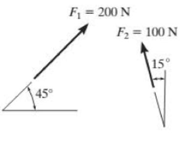
(a)
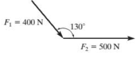
(b)
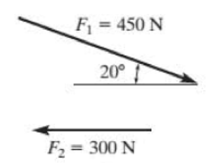
(c)
Prob. P2–1
Expert Solution & Answer

Learn your wayIncludes step-by-step video

schedule11:00
Students have asked these similar questions
Given answers to be: i) 14.65 kN; 6.16 kN; 8.46 kN ii) 8.63 kN; 9.88 kN iii) Bearing 6315 for B1 & B2, or Bearing 6215 for B1
(b)
A steel 'hot rolled structural hollow section' column of length 5.75 m, has
the cross-section shown in Figure Q.5(b) and supports a load of 750 kN.
During service, it is subjected to axial compression loading where one end
of the column is effectively restrained in position and direction (fixed) and
the other is effectively held in position but not in direction (pinned).
i)
Given that the steel has a design strength of 275 MN/m², determine
the load factor for the structural member based upon the BS5950
design approach using Datasheet Q.5(b).
[11]
ii)
Determine the axial load that can be supported by the column
using the Rankine-Gordon formula, given that the yield strength of
the material is 280 MN/m² and the constant *a* is 1/30000.
[6]
300
600
2-300 mm
wide x 5 mm
thick plates.
Figure Q.5(b)
L=5.75m
Pinned
Fixed
Help ارجو مساعدتي في حل هذا السؤال
Chapter 2 Solutions
Statics and Mechanics of Materials (5th Edition)
Ch. 2.3 - In each case, construct the parallelogram law to...Ch. 2.3 - In each case, show how to resolve the force F into...Ch. 2.3 - Determine the magnitude of the resultant force...Ch. 2.3 - Determine the magnitude of the resultant force....Ch. 2.3 - Determine the magnitude of the resultant force and...Ch. 2.3 - Resolve the 30-lb force into components along the...Ch. 2.3 - Resolve the force into components acting along...Ch. 2.3 - Prob. 6FPCh. 2.3 - If = 60 and F = 450 N, determine the magnitude of...Ch. 2.3 - If the magnitude of the resultant force is to be...
Ch. 2.3 - Determine the magnitude of the resultant force FR...Ch. 2.3 - Determine the magnitudes of the two components of...Ch. 2.3 - Solve Prob. 24 with F = 350 lb. 24. Determine the...Ch. 2.3 - Determine the magnitude of the resultant force FR...Ch. 2.3 - Resolve the force F1 into components acting along...Ch. 2.3 - Resolve the force F2 into components acting along...Ch. 2.3 - If the resultant force acting on the support is to...Ch. 2.3 - Determine the magnitude of the resultant force and...Ch. 2.3 - If = 60, determine the magnitude of the resultant...Ch. 2.3 - Determine the angle for connecting member A to...Ch. 2.3 - The force acting on the gear tooth is F = 20 lb....Ch. 2.3 - The component of force F acting along line aa is...Ch. 2.3 - Force F acts on the frame such that its component...Ch. 2.3 - Force F acts on the frame such that its component...Ch. 2.3 - If F1 = 30 lb and F2 = 40 lb, determine the angles...Ch. 2.3 - Determine the magnitude and direction of FA so...Ch. 2.3 - Determine the magnitude of the resultant force...Ch. 2.3 - Prob. 20PCh. 2.3 - If the resultant force of the two tugboats is 3...Ch. 2.3 - If FB = 3 kN and = 45, determine the magnitude of...Ch. 2.3 - If the resultant force of the two tugboats is...Ch. 2.4 - Resolve each force into its x and y components....Ch. 2.4 - F28. Determine the magnitude and direction of the...Ch. 2.4 - Prob. 9FPCh. 2.4 - Prob. 10FPCh. 2.4 - Prob. 11FPCh. 2.4 - Determine the magnitude of the resultant force and...Ch. 2.4 - Determine the magnitude of the resultant force and...Ch. 2.4 - Prob. 25PCh. 2.4 - Prob. 26PCh. 2.4 - Determine the magnitude of the resultant force and...Ch. 2.4 - Prob. 28PCh. 2.4 - Determine the magnitude of the resultant force...Ch. 2.4 - Prob. 30PCh. 2.4 - Prob. 31PCh. 2.4 - Prob. 32PCh. 2.4 - Determine the magnitude of the resultant force and...Ch. 2.4 - Prob. 34PCh. 2.4 - Prob. 35PCh. 2.4 - Determine the magnitude of the resultant force and...Ch. 2.4 - Determine the magnitude and direction of the...Ch. 2.6 - Sketch the following forces on the x, y, z...Ch. 2.6 - In each case, establish F as a Cartesian vector,...Ch. 2.6 - Show how to resolve each force into its x, y, z...Ch. 2.6 - Determine the coordinate direction angles of the...Ch. 2.6 - Prob. 14FPCh. 2.6 - Prob. 15FPCh. 2.6 - Prob. 16FPCh. 2.6 - Prob. 17FPCh. 2.6 - Determine the resultant force acting on the hook....Ch. 2.6 - The force F has a magnitude of 80 lb. Determine...Ch. 2.6 - The bolt is subjected to the force F, which has...Ch. 2.6 - Determine the magnitude and coordinate direction...Ch. 2.6 - Prob. 41PCh. 2.6 - Prob. 42PCh. 2.6 - Express each force in Cartesian vector form and...Ch. 2.6 - Prob. 44PCh. 2.6 - Determine the magnitude and coordinate direction...Ch. 2.6 - Determine the magnitude and coordinate direction...Ch. 2.6 - Prob. 47PCh. 2.6 - Determine the magnitude and coordinate direction...Ch. 2.6 - Prob. 49PCh. 2.6 - Prob. 50PCh. 2.6 - Prob. 51PCh. 2.6 - Determine the magnitude and coordinate direction...Ch. 2.6 - Prob. 53PCh. 2.6 - Prob. 54PCh. 2.6 - Determine the magnitude and coordinate direction...Ch. 2.8 - In each case, establish a position vector from...Ch. 2.8 - In each case, express F as a Cartesian vector. (a)...Ch. 2.8 - Prob. 19FPCh. 2.8 - Determine the length of the rod and the position...Ch. 2.8 - Prob. 21FPCh. 2.8 - Express the force as a Cartesian vector. Prob....Ch. 2.8 - Prob. 23FPCh. 2.8 - Prob. 24FPCh. 2.8 - Determine the length of the connecting rod AB by...Ch. 2.8 - Express force F as a Cartesian vector; then...Ch. 2.8 - Express each force as a Cartesian vector, and then...Ch. 2.8 - If F = {350i 250j 450k} N and cable AB is 9 m...Ch. 2.8 - The 8-m-long cable is anchored to the ground at A....Ch. 2.8 - The 8-m-long cable is anchored to the ground at A....Ch. 2.8 - Express each of the forces in Cartesian vector...Ch. 2.8 - If FB = 560 N and FC = 700 N, determine the...Ch. 2.8 - If FB = 700 N, and FC = 560 N, determine the...Ch. 2.8 - The plate is suspended using the three cables...Ch. 2.8 - Prob. 66PCh. 2.8 - Determine the magnitude and coordinate direction...Ch. 2.8 - Prob. 68PCh. 2.8 - The load at A creates a force of 60 lb in wire AB....Ch. 2.8 - Determine the magnitude and coordinate direction...Ch. 2.9 - In each case, set up the dot product to find the...Ch. 2.9 - In each case, set up the dot product to find the...Ch. 2.9 - Determine the angle between the force and the...Ch. 2.9 - Determine the angle between the force and the...Ch. 2.9 - Determine the angle between the force and the...Ch. 2.9 - Determine the projected component of the force...Ch. 2.9 - Find the magnitude of the projected component of...Ch. 2.9 - Determine the components of the force acting...Ch. 2.9 - Prob. 31FPCh. 2.9 - Prob. 71PCh. 2.9 - Determine the magnitudes of the components of F =...Ch. 2.9 - Determine the angle between BA and BC. Probs. 273Ch. 2.9 - Determine the magnitude of the projected component...Ch. 2.9 - Prob. 75PCh. 2.9 - Determine the magnitude of the projection of the...Ch. 2.9 - Determine the angle between the pole and the wire...Ch. 2.9 - Determine the magnitude of the projection of the...Ch. 2.9 - Determine the magnitude of the projected component...Ch. 2.9 - Prob. 80PCh. 2.9 - Determine the angle between the two cables. Prob....Ch. 2.9 - Determine the projected component of the force...Ch. 2.9 - Determine the angles and between the flag pole...Ch. 2.9 - Determine the magnitudes of the components of F...Ch. 2.9 - Prob. 85PCh. 2.9 - Determine the angle between the pipe segments BA...Ch. 2.9 - If the force F = 100 N lies in the plane DBEC,...Ch. 2.9 - Determine the magnitudes of the components of the...Ch. 2.9 - Determine the magnitudes of the projected...Ch. 2.9 - Determine the magnitude of the projected component...Ch. 2.9 - Two cables exert forces on the pipe. Determine the...Ch. 2.9 - Determine the angle between the two forces. Prob....Ch. 2 - Determine the magnitude of the resultant force FR...Ch. 2 - Resolve the force into components along the u and...Ch. 2 - Determine the magnitude of the resultant force...Ch. 2 - The cable exerts a force of 250 lb on the crane...Ch. 2 - The cable attached to the tractor at B exerts a...Ch. 2 - Express F1 and F2 as Cartesian vectors. Prob. R26Ch. 2 - Determine the angle between the edges of the...Ch. 2 - Determine the projection of the force F along the...
Additional Engineering Textbook Solutions
Find more solutions based on key concepts
Kilometer Converter Design a modular program that asks the user to enter a distance in kilometers, and then con...
Starting Out with Programming Logic and Design (5th Edition) (What's New in Computer Science)
Area Class Write a class that has three overloaded static methods for calculating the areas of the following ge...
Starting Out with Java: From Control Structures through Data Structures (4th Edition) (What's New in Computer Science)
Give an example of each of the following, other than those described in this chapter, and clearly explain why y...
Modern Database Management
In Exercises 41 through 46, identify the errors. Dima,b,c,dAsDoublea=2b=3c=d=4Istoutput.Items.Add(5((a+b)/(c+d)
Introduction To Programming Using Visual Basic (11th Edition)
In programming we use the term string to mean _____. a. many lines of code b. parallel memory locations c. stri...
Starting Out With Visual Basic (8th Edition)
Can a class contain both instance variables and static methods?
Java: An Introduction to Problem Solving and Programming (8th Edition)
Knowledge Booster


Learn more about
Need a deep-dive on the concept behind this application? Look no further. Learn more about this topic, mechanical-engineering and related others by exploring similar questions and additional content below.Similar questions
- Q10) Body A weighs 600 lb contact with smooth surfaces at D and E. Determine the tension in the cord and the forces acting on C on member BD, also calculate the reaction at B and F. Cable 6' 3' wwwarrow_forwardHelp ارجو مساعدتي في حل هذا السؤالarrow_forwardQ3: Find the resultant of the force system.arrow_forward
- Question 1 A three-blade propeller of a diameter of 2 m has an activity factor AF of 200 and its ratio of static thrust coefficient to static torque coefficient is 10. The propeller's integrated lift coefficient is 0.3.arrow_forward(L=6847 mm, q = 5331 N/mm, M = 1408549 N.mm, and El = 8.6 x 10¹⁴ N. mm²) X A ΕΙ B L Y Marrow_forwardCalculate the maximum shear stress Tmax at the selected element within the wall (Fig. Q3) if T = 26.7 KN.m, P = 23.6 MPa, t = 2.2 mm, R = 2 m. The following choices are provided in units of MPa and rounded to three decimal places. Select one: ○ 1.2681.818 O 2. 25745.455 O 3. 17163.636 O 4. 10727.273 ○ 5.5363.636arrow_forward
- If L-719.01 mm, = 7839.63 N/m³, the normal stress σ caused by self-weight at the location of the maximum normal stress in the bar can be calculated as (Please select the correct value of σ given in Pa and rounded to three decimal places.) Select one: ○ 1. 1409.193 2. 845.516 O 3. 11273.545 ○ 4.8455.159 ○ 5.4509.418 6. 2818.386 7.5636.772arrow_forwardTo calculate the rotation at Point B, a suitable virtual structure needs to be created. Which equation in the following choices most accurately represents the functional relationship between the bending moment, Mv2 ( Units: N.mm), of the virtual structure and the spatial coordinate x (Units: mm) if the applied unit virtual moment is clockwise? Select one: O 1. Mv2 1.000 O 2. Mv2=x+1.000 O 3. Mv2=x+0.000 4. Mv2 = -x-1.000 O 5. Mv2 -1.000 6. Mv2=-x+0.000arrow_forwardThe vertical deflection at Point B can be calculated as ( The following choices are provided in units of mm and rounded to three decimal places ; the downward deflection is negative and upward deflection is positive. ) Select one: 1. 1703.065 2. -1703.065 3. -2043.679 4.1362.452 5. -1362.452 6. 2043.679arrow_forward
arrow_back_ios
SEE MORE QUESTIONS
arrow_forward_ios
Recommended textbooks for you
 Elements Of ElectromagneticsMechanical EngineeringISBN:9780190698614Author:Sadiku, Matthew N. O.Publisher:Oxford University Press
 Mechanics of Materials (10th Edition)Mechanical EngineeringISBN:9780134319650Author:Russell C. HibbelerPublisher:PEARSON
 Thermodynamics: An Engineering ApproachMechanical EngineeringISBN:9781259822674Author:Yunus A. Cengel Dr., Michael A. BolesPublisher:McGraw-Hill Education
 Control Systems EngineeringMechanical EngineeringISBN:9781118170519Author:Norman S. NisePublisher:WILEY
 Mechanics of Materials (MindTap Course List)Mechanical EngineeringISBN:9781337093347Author:Barry J. Goodno, James M. GerePublisher:Cengage Learning
 Engineering Mechanics: StaticsMechanical EngineeringISBN:9781118807330Author:James L. Meriam, L. G. Kraige, J. N. BoltonPublisher:WILEY
Elements Of Electromagnetics
Mechanical Engineering
ISBN:9780190698614
Author:Sadiku, Matthew N. O.
Publisher:Oxford University Press
Mechanics of Materials (10th Edition)
Mechanical Engineering
ISBN:9780134319650
Author:Russell C. Hibbeler
Publisher:PEARSON
Thermodynamics: An Engineering Approach
Mechanical Engineering
ISBN:9781259822674
Author:Yunus A. Cengel Dr., Michael A. Boles
Publisher:McGraw-Hill Education
Control Systems Engineering
Mechanical Engineering
ISBN:9781118170519
Author:Norman S. Nise
Publisher:WILEY
Mechanics of Materials (MindTap Course List)
Mechanical Engineering
ISBN:9781337093347
Author:Barry J. Goodno, James M. Gere
Publisher:Cengage Learning
Engineering Mechanics: Statics
Mechanical Engineering
ISBN:9781118807330
Author:James L. Meriam, L. G. Kraige, J. N. Bolton
Publisher:WILEY
How to balance a see saw using moments example problem; Author: Engineer4Free;https://www.youtube.com/watch?v=d7tX37j-iHU;License: Standard Youtube License