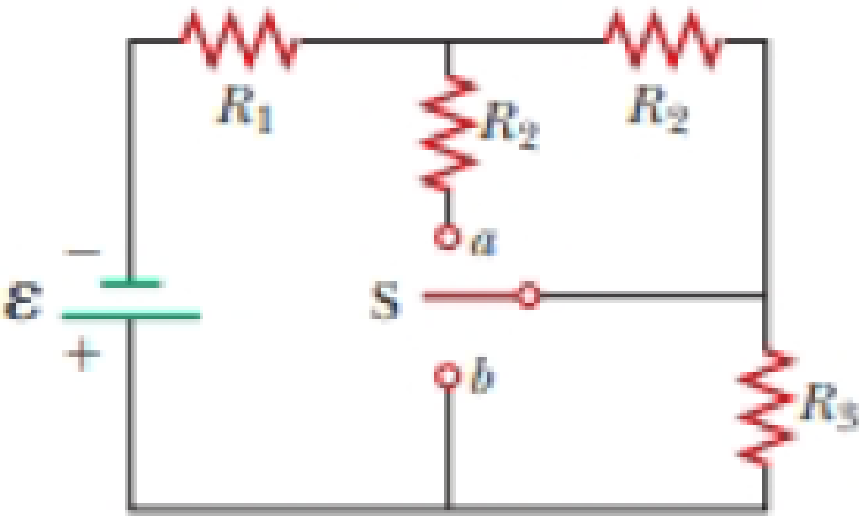
A battery with ε = 6.00 V and no internal resistance supplies current to the circuit shown in Figure P27.9. When the double-throw switch S is open as shown in the figure, the current in the battery is 1.00 mA. When the switch is closed in position a, the current in the battery is 1.20 mA. When the switch is closed in position b, the current in the battery is 2.00 mA. Find the resistances (a) R1, (b) R2, and (c) R3.
Figure P27.9 Problems 9 and 10.

Want to see the full answer?
Check out a sample textbook solution
Chapter 27 Solutions
Bundle: Physics For Scientists And Engineers With Modern Physics, 10th + Webassign Printed Access Card For Serway/jewett's Physics For Scientists And Engineers, 10th, Multi-term
Additional Science Textbook Solutions
Chemistry: Atoms First
Campbell Biology (11th Edition)
SEELEY'S ANATOMY+PHYSIOLOGY
Organic Chemistry
General, Organic, and Biological Chemistry: Structures of Life (5th Edition)
Microbiology Fundamentals: A Clinical Approach
- The shear leg derrick is used to haul the 200-kg net of fish onto the dock as shown in. Assume the force in each leg acts along its axis. 5.6 m. 4 m- B Part A Determine the compressive force along leg AB. Express your answer to three significant figures and include the appropriate units. FAB = Value Submit Request Answer Part B Units ? Determine the compressive force along leg CB. Express your answer to three significant figures and include the appropriate units. FCB= Value Submit Request Answer Part C ? Units Determine the tension in the winch cable DB. Express your answer with the appropriate units. 2marrow_forwardPart A (Figure 1) shows a bucket suspended from a cable by means of a small pulley at C. If the bucket and its contents have a mass of 10 kg, determine the location of the pulley for equilibrium. The cable is 6 m long. Express your answer to three significant figures and include the appropriate units. Figure 4 m B НА x = Value Submit Request Answer Provide Feedback < 1 of 1 T 1 m Units ?arrow_forwardThe particle in is in equilibrium and F4 = 165 lb. Part A Determine the magnitude of F1. Express your answer in pounds to three significant figures. ΑΣΦ tvec F₁ = Submit Request Answer Part B Determine the magnitude of F2. Express your answer in pounds to three significant figures. ΑΣΦ It vec F2 = Submit Request Answer Part C Determine the magnitude of F3. Express your answer in pounds to three significant figures. ? ? lb lb F₂ 225 lb 135° 45° 30° -60°-arrow_forward
- The 10-lb weight is supported by the cord AC and roller and by the spring that has a stiffness of k = 10 lb/in. and an unstretched length of 12 in. as shown in. Part A Determine the distance d to maintain equilibrium. Express your answer in inches to three significant figures. 節 ΕΠΙ ΑΣΦ d = *k J vec 5 t 0 ? d C A in. 12 in. Barrow_forwardThe members of a truss are connected to the gusset plate as shown in . The forces are concurrent at point O. Take = 90° and T₁ = 7.5 kN. Part A Determine the magnitude of F for equilibrium. Express your answer to three significant figures and include the appropriate units. F = Value Submit Request Answer Part B 0 ? Units Determine the magnitude of T2 for equilibrium. Express your answer to three significant figures and include the appropriate units. ? T₂ = Value Units T₁ Carrow_forwardpls help on botharrow_forward
- pls helparrow_forwardpls helparrow_forward6. 6. There are 1000 turns on the primary side of a transformer and 200 turns on thesecondary side. If 440 V are supplied to the primary winding, what is the voltageinduced in the secondary winding? Is this a step-up or step-down transformer? 7. 80 V are supplied to the primary winding of a transformer that has 50 turns. If thesecondary side has 50,000 turns, what is the voltage induced on the secondary side?Is this a step-up or step-down transformer? 8. There are 50 turns on the primary side of a transformer and 500 turns on thesecondary side. The current through the primary winding is 6 A. What is the turnsratio of this transformer? What is the current, in milliamps, through the secondarywinding?9. The current through the primary winding on a transformer is 5 A. There are 1000turns on the primary winding and 20 turns on the secondary winding. What is theturns ratio of this transformer? What is the current, in amps, through the secondarywinding?arrow_forward
- No chatgpt plsarrow_forwardWhat is the current, in amps, across a conductor that has a resistance of10 Ω and a voltage of 20 V? 2. A conductor draws a current of 100 A and a resistance of 5 Ω. What is thevoltageacross the conductor? 3. What is the resistance, in ohm’s, of a conductor that has a voltage of 80 kVand acurrent of 200 mA? 4. An x-ray imaging system that draws a current of 90 A is supplied with 220V. What is the power consumed? 5. An x-ray is produced using 800 mA and 100 kV. What is the powerconsumed in kilowatts?arrow_forwardՍՈՈՒ XVirginia Western Community Coll x P Course Home X + astering.pearson.com/?courseld=13289599#/ Figure y (mm) x=0x = 0.0900 m All ✓ Correct For either the time for one full cycle is 0.040 s; this is the period. Part C - ON You are told that the two points x = 0 and x = 0.0900 m are within one wavelength of each other. If the wave is moving in the +x-direction, determine the wavelength. Express your answer to two significant figures and include the appropriate units. 0 t(s) λ = Value m 0.01 0.03 0.05 0.07 Copyright © 2025 Pearson Education Inc. All rights reserved. 日 F3 F4 F5 1775 % F6 F7 B F8 Submit Previous Answers Request Answer ? × Incorrect; Try Again; 3 attempts remaining | Terms of Use | Privacy Policy | Permissions | Contact Us | Cookie Settings 28°F Clear 4 9:23 PM 1/20/2025 F9 prt sc F10 home F11 end F12 insert delete 6 7 29 & * ( 8 9 0 t = back Οarrow_forward
 Physics for Scientists and Engineers with Modern ...PhysicsISBN:9781337553292Author:Raymond A. Serway, John W. JewettPublisher:Cengage Learning
 Physics for Scientists and EngineersPhysicsISBN:9781337553278Author:Raymond A. Serway, John W. JewettPublisher:Cengage Learning
 Physics for Scientists and Engineers: Foundations...PhysicsISBN:9781133939146Author:Katz, Debora M.Publisher:Cengage Learning
 Principles of Physics: A Calculus-Based TextPhysicsISBN:9781133104261Author:Raymond A. Serway, John W. JewettPublisher:Cengage Learning
 Physics for Scientists and Engineers, Technology ...PhysicsISBN:9781305116399Author:Raymond A. Serway, John W. JewettPublisher:Cengage Learning
 College PhysicsPhysicsISBN:9781305952300Author:Raymond A. Serway, Chris VuillePublisher:Cengage Learning


