Bundle: Physics For Scientists And Engineers With Modern Physics, 10th + Webassign Printed Access Card For Serway/jewett's Physics For Scientists And Engineers, 10th, Multi-term
10th Edition
ISBN: 9781337888516
Author: Raymond A. Serway, John W. Jewett
Publisher: Cengage Learning
expand_more
expand_more
format_list_bulleted
Videos
Textbook Question
Chapter 27, Problem 26P
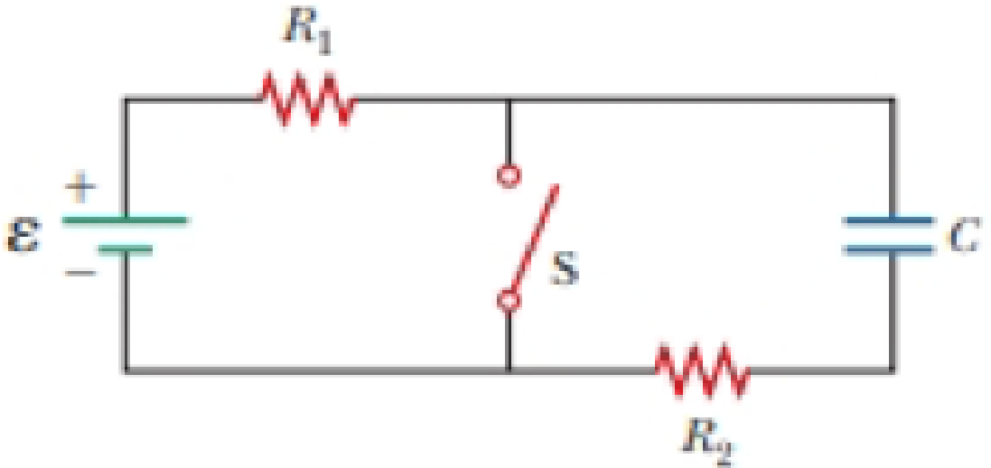
In the circuit of Figure P27.25, the switch S has been open for a long time. It is then suddenly closed. Determine the time constant (a) before the switch is closed and (b) after the switch is closed. (c) Let the switch be closed at t = 0. Determine the current in the switch as a function of time.
Figure P27.25 Problems 25 and 26.
Expert Solution & Answer
Want to see the full answer?
Check out a sample textbook solution
Students have asked these similar questions
the cable may break and cause severe injury.
cable is more likely to break as compared to the
[1]
ds, inclined at angles of 30° and 50° to the vertical
rings by way of a scaled diagram. [4]
I
30°
T₁
3cm
3.8T2
cm
200 N
50°
at it is headed due North and its airspeed indicat
240 km/h. If there is a wind of 100 km/h from We
e relative to the Earth? [3]
Can you explain this using nodal analysis
With the nodes I have present
And then show me how many KCL equations I need to write, I’m thinking 2 since we have 2 dependent sources
state the difference between vector and scalar qu
Chapter 27 Solutions
Bundle: Physics For Scientists And Engineers With Modern Physics, 10th + Webassign Printed Access Card For Serway/jewett's Physics For Scientists And Engineers, 10th, Multi-term
Ch. 27.1 - To maximize the percentage of the power from the...Ch. 27.2 - With the switch in the circuit of Figure 27.4a...Ch. 27.2 - With the switch in the circuit of Figure 27.6a...Ch. 27.2 - Prob. 27.4QQCh. 27.4 - Consider the circuit in Figure 27.17 and assume...Ch. 27 - Two 1.50-V batterieswith their positive terminals...Ch. 27 - As in Example 27.2, consider a power supply with...Ch. 27 - Figure P27.3 shows the interior of a three-way...Ch. 27 - Prob. 4PCh. 27 - Consider the two circuits shown in Figure P27.5 in...
Ch. 27 - Consider strings of incandescent lights that are...Ch. 27 - You are working at an electronics fabrication...Ch. 27 - In your new job at an engineering company, your...Ch. 27 - A battery with = 6.00 V and no internal...Ch. 27 - A battery with emf and no internal resistance...Ch. 27 - Todays class on current and resistance is about to...Ch. 27 - Why is the following situation impossible? A...Ch. 27 - Calculate the power delivered to each resistor in...Ch. 27 - For the purpose of measuring the electric...Ch. 27 - Four resistors are connected to a battery as shown...Ch. 27 - You have a faculty position at a community college...Ch. 27 - The circuit shown in Figure P27.17 is connected...Ch. 27 - The following equations describe an electric...Ch. 27 - Taking R = 1.00 k and = 250 V in Figure P27.19,...Ch. 27 - In the circuit of Figure P27.20, the current I1 =...Ch. 27 - (a) Can the circuit shown in Figure P27.21 be...Ch. 27 - For the circuit shown in Figure P27.22, we wish to...Ch. 27 - An uncharged capacitor and a resistor are...Ch. 27 - Prob. 24PCh. 27 - In the circuit of Figure P27.25, the switch S has...Ch. 27 - In the circuit of Figure P27.25, the switch S has...Ch. 27 - A 10.0-F capacitor is charged by a 10.0-V battery...Ch. 27 - Prob. 28PCh. 27 - Prob. 29PCh. 27 - Prob. 30PCh. 27 - Prob. 31PCh. 27 - Prob. 32APCh. 27 - Find the equivalent resistance between points a...Ch. 27 - The circuit in Figure P27.34a consists of three...Ch. 27 - The circuit in Figure P27.35 has been connected...Ch. 27 - The resistance between terminals a and b in Figure...Ch. 27 - (a) Calculate the potential difference between...Ch. 27 - Why is the following situation impossible? A...Ch. 27 - When two unknown resistors are connected in series...Ch. 27 - Prob. 40APCh. 27 - The circuit in Figure P27.41 contains two...Ch. 27 - Prob. 42APCh. 27 - A power supply has an open-circuit voltage of 40.0...Ch. 27 - A battery is used to charge a capacitor through a...Ch. 27 - Prob. 45APCh. 27 - (a) Determine the equilibrium charge on the...Ch. 27 - In Figure P27.47, suppose the switch has been...Ch. 27 - Figure P27.48 shows a circuit model for the...Ch. 27 - The student engineer of a campus radio station...Ch. 27 - Prob. 50APCh. 27 - The switch in Figure P27.51a closes when Vc23Vand...
Additional Science Textbook Solutions
Find more solutions based on key concepts
How does the removal of hydrogen atoms from nutrient molecules result in a loss of energy from the nutrient mol...
SEELEY'S ANATOMY+PHYSIOLOGY
Sea turtles have disappeared from many regions, and one way of trying to save them is to reintroduce them to ar...
MARINE BIOLOGY
What process causes the Mediterranean intermediate Water MIW to become more dense than water in the adjacent At...
Applications and Investigations in Earth Science (9th Edition)
Define histology.
Fundamentals of Anatomy & Physiology (11th Edition)
On what molecule does the anticodon appear? Explain the role of this molecule in protein synthesis.
Human Physiology: An Integrated Approach (8th Edition)
Separate the list P,F,V,,T,a,m,L,t, and V into intensive properties, extensive properties, and nonproperties.
Fundamentals Of Thermodynamics
Knowledge Booster


Learn more about
Need a deep-dive on the concept behind this application? Look no further. Learn more about this topic, physics and related others by exploring similar questions and additional content below.Similar questions
- Please don't use Chatgpt will upvote and give handwritten solutionarrow_forwardNo chatgpt pls will upvotearrow_forwardThe shear leg derrick is used to haul the 200-kg net of fish onto the dock as shown in. Assume the force in each leg acts along its axis. 5.6 m. 4 m- B Part A Determine the compressive force along leg AB. Express your answer to three significant figures and include the appropriate units. FAB = Value Submit Request Answer Part B Units ? Determine the compressive force along leg CB. Express your answer to three significant figures and include the appropriate units. FCB= Value Submit Request Answer Part C ? Units Determine the tension in the winch cable DB. Express your answer with the appropriate units. 2marrow_forward
- Part A (Figure 1) shows a bucket suspended from a cable by means of a small pulley at C. If the bucket and its contents have a mass of 10 kg, determine the location of the pulley for equilibrium. The cable is 6 m long. Express your answer to three significant figures and include the appropriate units. Figure 4 m B НА x = Value Submit Request Answer Provide Feedback < 1 of 1 T 1 m Units ?arrow_forwardThe particle in is in equilibrium and F4 = 165 lb. Part A Determine the magnitude of F1. Express your answer in pounds to three significant figures. ΑΣΦ tvec F₁ = Submit Request Answer Part B Determine the magnitude of F2. Express your answer in pounds to three significant figures. ΑΣΦ It vec F2 = Submit Request Answer Part C Determine the magnitude of F3. Express your answer in pounds to three significant figures. ? ? lb lb F₂ 225 lb 135° 45° 30° -60°-arrow_forwardThe 10-lb weight is supported by the cord AC and roller and by the spring that has a stiffness of k = 10 lb/in. and an unstretched length of 12 in. as shown in. Part A Determine the distance d to maintain equilibrium. Express your answer in inches to three significant figures. 節 ΕΠΙ ΑΣΦ d = *k J vec 5 t 0 ? d C A in. 12 in. Barrow_forward
- The members of a truss are connected to the gusset plate as shown in . The forces are concurrent at point O. Take = 90° and T₁ = 7.5 kN. Part A Determine the magnitude of F for equilibrium. Express your answer to three significant figures and include the appropriate units. F = Value Submit Request Answer Part B 0 ? Units Determine the magnitude of T2 for equilibrium. Express your answer to three significant figures and include the appropriate units. ? T₂ = Value Units T₁ Carrow_forwardpls help on botharrow_forwardpls helparrow_forward
- pls helparrow_forward6. 6. There are 1000 turns on the primary side of a transformer and 200 turns on thesecondary side. If 440 V are supplied to the primary winding, what is the voltageinduced in the secondary winding? Is this a step-up or step-down transformer? 7. 80 V are supplied to the primary winding of a transformer that has 50 turns. If thesecondary side has 50,000 turns, what is the voltage induced on the secondary side?Is this a step-up or step-down transformer? 8. There are 50 turns on the primary side of a transformer and 500 turns on thesecondary side. The current through the primary winding is 6 A. What is the turnsratio of this transformer? What is the current, in milliamps, through the secondarywinding?9. The current through the primary winding on a transformer is 5 A. There are 1000turns on the primary winding and 20 turns on the secondary winding. What is theturns ratio of this transformer? What is the current, in amps, through the secondarywinding?arrow_forwardNo chatgpt plsarrow_forward
arrow_back_ios
SEE MORE QUESTIONS
arrow_forward_ios
Recommended textbooks for you
 Physics for Scientists and EngineersPhysicsISBN:9781337553278Author:Raymond A. Serway, John W. JewettPublisher:Cengage Learning
 Physics for Scientists and Engineers with Modern ...PhysicsISBN:9781337553292Author:Raymond A. Serway, John W. JewettPublisher:Cengage Learning
 Principles of Physics: A Calculus-Based TextPhysicsISBN:9781133104261Author:Raymond A. Serway, John W. JewettPublisher:Cengage Learning
 Physics for Scientists and Engineers: Foundations...PhysicsISBN:9781133939146Author:Katz, Debora M.Publisher:Cengage Learning
 Physics for Scientists and Engineers, Technology ...PhysicsISBN:9781305116399Author:Raymond A. Serway, John W. JewettPublisher:Cengage Learning
Physics for Scientists and Engineers
Physics
ISBN:9781337553278
Author:Raymond A. Serway, John W. Jewett
Publisher:Cengage Learning
Physics for Scientists and Engineers with Modern ...
Physics
ISBN:9781337553292
Author:Raymond A. Serway, John W. Jewett
Publisher:Cengage Learning
Principles of Physics: A Calculus-Based Text
Physics
ISBN:9781133104261
Author:Raymond A. Serway, John W. Jewett
Publisher:Cengage Learning
Physics for Scientists and Engineers: Foundations...
Physics
ISBN:9781133939146
Author:Katz, Debora M.
Publisher:Cengage Learning
Physics for Scientists and Engineers, Technology ...
Physics
ISBN:9781305116399
Author:Raymond A. Serway, John W. Jewett
Publisher:Cengage Learning
What is Electromagnetic Induction? | Faraday's Laws and Lenz Law | iKen | iKen Edu | iKen App; Author: Iken Edu;https://www.youtube.com/watch?v=3HyORmBip-w;License: Standard YouTube License, CC-BY