
Physics for Scientists and Engineers with Modern Physics
4th Edition
ISBN: 9780131495081
Author: Douglas C. Giancoli
Publisher: Addison-Wesley
expand_more
expand_more
format_list_bulleted
Concept explainers
Videos
Textbook Question
Chapter 26, Problem 28P
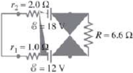
(II) Determine the terminal voltage of each battery in Fig. 26–46.
FIGURE 26–46 Problem 28.
Expert Solution & Answer
Want to see the full answer?
Check out a sample textbook solution
Students have asked these similar questions
l
No chatgpt pls will upvote Already got wrong chatgpt answer
No chatgpt pls
Chapter 26 Solutions
Physics for Scientists and Engineers with Modern Physics
Ch. 26.1 - Repeat Example 261 assuming now that the...Ch. 26.2 - You have a 10- and a 15- resistor. What is the...Ch. 26.3 - Write the equation for the lower loop abcdefga of...Ch. 26.4 - If the jumper cables of Example 2610 were...Ch. 26.5 - In 10 times constants, the charge on the capacitor...Ch. 26 - Explain why birds can sit on power lines safely,...Ch. 26 - Discuss the advantages and disadvantages of...Ch. 26 - If all you have is a 120-V line, would it be...Ch. 26 - Two lightbulbs of resistance R1 and R2 (R2 R1)...Ch. 26 - Household outlets are often double outlets. Are...
Ch. 26 - With two identical lightbulbs and two identical...Ch. 26 - If two identical resistors are connected in series...Ch. 26 - You have a single 60-W bulb on in your room. How...Ch. 26 - When applying Kirchhoffs loop rule (such as in...Ch. 26 - Compare and discuss the formulas for resistors and...Ch. 26 - For what use are batteries connected in series?...Ch. 26 - Can the terminal voltage of a battery ever exceed...Ch. 26 - Explain in detail how you could measure the...Ch. 26 - In an RC circuit, current flows from the battery...Ch. 26 - Given the circuit shown in Fig. 2634, use the...Ch. 26 - Figure 2635 is a diagram of a capacitor (or...Ch. 26 - Design a circuit in which two different switches...Ch. 26 - What is the main difference between an analog...Ch. 26 - What would happen if you mistakenly used an...Ch. 26 - Explain why an ideal ammeter would have zero...Ch. 26 - A voltmeter connected across a resistor always...Ch. 26 - A small battery-operated flashlight requires a...Ch. 26 - Different lamps might have batteries connected in...Ch. 26 - Prob. 1PCh. 26 - (I) Four 1.50-V cells are connected in series to a...Ch. 26 - (II) A 1.5-V dry cell can be tested by connecting...Ch. 26 - (II) What is the internal resistance of a 12.0-V...Ch. 26 - (I) A 650- and a 2200- resistor are connected in...Ch. 26 - (I) Three 45- lightbulbs and three 65- lightbulbs...Ch. 26 - (I) Suppose that you have a 680-, a 720-, and a...Ch. 26 - (I) How many 10- resistors must be connected in...Ch. 26 - (II) Suppose that you have a 9.0-V battery and you...Ch. 26 - Three 1.70-k resistors can be connected together...Ch. 26 - (II) A battery with an emf of 12.0 V shows a...Ch. 26 - (II) Eight identical bulbs are connected in series...Ch. 26 - (II) Eight bulbs are connected in parallel to a...Ch. 26 - (II) The performance of the starter circuit in an...Ch. 26 - (II) A close inspection of an electric circuit...Ch. 26 - (II) Determine (a) the equivalent resistance of...Ch. 26 - (II) A 75-W, 110-V bulb is connected in parallel...Ch. 26 - (II) (a) Determine the equivalent resistance of...Ch. 26 - (II) Whal is the net resistance of the circuit...Ch. 26 - (II) Calculate the current through each resistor...Ch. 26 - (II) The two terminals of a voltage source with...Ch. 26 - (II) Two resistors when connected in series to a...Ch. 26 - (III) Three equal resistors (R) are connected to a...Ch. 26 - (III) A 2.8-k and a 3.7-k resistor are connected...Ch. 26 - (III) Consider the network of resistors shown in...Ch. 26 - (III) You are designing a wire resistance heater...Ch. 26 - (I) Calculate the current in the circuit of Fig....Ch. 26 - (II) Determine the terminal voltage of each...Ch. 26 - (II) For the circuit shown in Fig. 2647, find the...Ch. 26 - (II) (a) A network of five equal resistors R is...Ch. 26 - (II) (a) What is the potential difference between...Ch. 26 - (II) Calculate the currents in each resistor of...Ch. 26 - (II) Determine the magnitudes and directions of...Ch. 26 - (II) Determine the magnitudes and directions of...Ch. 26 - (II) A voltage V is applied to n identical...Ch. 26 - (III) (a) Determine the currents I1, I2, and I3 in...Ch. 26 - (III) What would the current I1 be in Fig. 2653 if...Ch. 26 - (III) Determine the current through each of the...Ch. 26 - (III) If the 25- resistor in Fig. 2654 is shorted...Ch. 26 - (III) Twelve resistors, each of resistance R, are...Ch. 26 - (III) Determine the net resistance in Fig. 2656...Ch. 26 - (II) Suppose two batteries, with unequal emfs of...Ch. 26 - (I) Estimate the range of resistance needed to...Ch. 26 - (II) In Fig. 2658 (same as Fig. 2617a), the total...Ch. 26 - (II) Two 3.8-F capacitors, two 2.2-k resistors,...Ch. 26 - (II) How long does it take for the energy stored...Ch. 26 - (II) A parallel-plate capacitor is filled with a...Ch. 26 - (II) The RC circuit of Fig. 2659 (same as Fig....Ch. 26 - (II) Consider the circuit shown in Fig. 2660,...Ch. 26 - (III) Determine the time constant for charging the...Ch. 26 - (III) Two resistors and two uncharged capacitors...Ch. 26 - (III) Suppose the switch S in Fig. 2662 is closed....Ch. 26 - (I) An ammeter has a sensitivity of 35,00 /V. What...Ch. 26 - (I) What is the resistance of a voltmeter on the...Ch. 26 - (II) A galvanometer has a sensitivity of 45 k/V...Ch. 26 - (II) A galvanometer has an internal resistance of...Ch. 26 - (II) A particular digital meter is based on an...Ch. 26 - (II) A milliammeter reads 25 mA full scale. It...Ch. 26 - (II) A 45-V battery of negligible internal...Ch. 26 - (II) An ammeter whose internal resistance is 53 ...Ch. 26 - (II) A battery with E=12.0V and internal...Ch. 26 - (II) A 12.0-V battery (assume the internal...Ch. 26 - (III) Two 9.4-k resistors are placed in series and...Ch. 26 - (III) When the resistor R in Fig. 2664 is 35 , the...Ch. 26 - Suppose that you wish to apply a 0.25-V potential...Ch. 26 - A three-way lightbulb can produce 50 W, 100 W, or...Ch. 26 - Suppose you want to run some apparatus that is 65...Ch. 26 - For the circuit shown in Fig. 2618a, show that the...Ch. 26 - A heart pacemaker is designed to operate at 72...Ch. 26 - Prob. 70GPCh. 26 - A Wheatstone bridge is a type of bridge circuit...Ch. 26 - An unknown length of platinum wire 1.22 mm in...Ch. 26 - The internal resistance of a 1.35-V mercury cell...Ch. 26 - How many 12-W resistors, each of the same...Ch. 26 - A solar cell, 3.0 cm square, has an output of 350...Ch. 26 - A power supply has a fixed output voltage of 12.0...Ch. 26 - The current through the 4.0-k resistor in Fig....Ch. 26 - A battery produces 40.8 V when 7.40 A is drawn...Ch. 26 - In the circuit shown in Fig. 2668, the 33-...Ch. 26 - The current through the 20- resistor in Fig. 2669...Ch. 26 - (a) A voltmeter and an ammeter can be connected as...Ch. 26 - (a) What is the equivalent resistance of the...Ch. 26 - A flashlight bulb rated at 2.0 W and 3.0 V is...Ch. 26 - Some light-dimmer switches use a variable resistor...Ch. 26 - A potentiometer is a device to precisely measure...Ch. 26 - Electronic devices often use an RC circuit to...Ch. 26 - The circuit shown in Fig. 2676 is a primitive...Ch. 26 - Determine the current in each resistor of the...Ch. 26 - In the circuit shown in Fig. 2678, switch S is...Ch. 26 - Figure 2679 shows the circuit for a simple...Ch. 26 - Measurements made on circuits that contain large...Ch. 26 - A typical voltmeter has an internal resistance of...Ch. 26 - (II) An RC series circuit contains a resistor R =...
Additional Science Textbook Solutions
Find more solutions based on key concepts
Why is petroleum jelly used in the hanging-drop procedure?
Laboratory Experiments in Microbiology (12th Edition) (What's New in Microbiology)
Identify each of the following characteristics as belonging to cervical, thoracic, or lumbar vertebrae; the sac...
Human Anatomy & Physiology (2nd Edition)
Write a balanced chemical equation for each chemical reaction. a. Solid copper reacts with solid sulfur to form...
Introductory Chemistry (6th Edition)
1.3 Obtain a bottle of multivitamins and read the list of ingredients. What are four chemicals from the list?
Chemistry: An Introduction to General, Organic, and Biological Chemistry (13th Edition)
Explain all answer clearly, with complete sentences and proper essay structure if needed. An asterisk (*) desig...
Cosmic Perspective Fundamentals
1. Which is a function of the skeletal system? (a) support, (b) hematopoietic site, (c) storage, (d) providing ...
Anatomy & Physiology (6th Edition)
Knowledge Booster


Learn more about
Need a deep-dive on the concept behind this application? Look no further. Learn more about this topic, physics and related others by exploring similar questions and additional content below.Similar questions
- help me with the experimental set up for the excel i did. the grapharrow_forwardWhich of the following best describes how to calculate the average acceleration of any object? Average acceleration is always halfway between the initial acceleration of an object and its final acceleration. Average acceleration is always equal to the change in velocity of an object divided by the time interval. Average acceleration is always equal to the displacement of an object divided by the time interval. Average acceleration is always equal to the change in speed of an object divided by the time interval.arrow_forwardThe figure shows the velocity versus time graph for a car driving on a straight road. Which of the following best describes the acceleration of the car? v (m/s) t(s) The acceleration of the car is negative and decreasing. The acceleration of the car is constant. The acceleration of the car is positive and increasing. The acceleration of the car is positive and decreasing. The acceleration of the car is negative and increasing.arrow_forward
- Which figure could represent the velocity versus time graph of a motorcycle whose speed is increasing? v (m/s) v (m/s) t(s) t(s)arrow_forwardUnlike speed, velocity is a the statement? Poisition. Direction. Vector. Scalar. quantity. Which one of the following completesarrow_forwardNo chatgpt pls will upvote Already got wrong chatgpt answerarrow_forward
- 3.63 • Leaping the River II. A physics professor did daredevil stunts in his spare time. His last stunt was an attempt to jump across a river on a motorcycle (Fig. P3.63). The takeoff ramp was inclined at 53.0°, the river was 40.0 m wide, and the far bank was 15.0 m lower than the top of the ramp. The river itself was 100 m below the ramp. Ignore air resistance. (a) What should his speed have been at the top of the ramp to have just made it to the edge of the far bank? (b) If his speed was only half the value found in part (a), where did he land? Figure P3.63 53.0° 100 m 40.0 m→ 15.0 marrow_forwardPlease solve and answer the question correctly please. Thank you!!arrow_forwardYou throw a small rock straight up from the edge of a highway bridge that crosses a river. The rock passes you on its way down, 5.00 s after it was thrown. What is the speed of the rock just before it reaches the water 25.0 m below the point where the rock left your hand? Ignore air resistance.arrow_forward
- Help me make a visualize experimental setup using a word document. For the theory below.arrow_forwardHow to solve this, given answerarrow_forwardThree point-like charges are placed at the corners of a square as shown in the figure, 28.0 cm on each side. Find the minimum amount of work required by an external force to move the charge q1 to infinity. Let q1=-2.10 μC, q2=+2.40 μС, q3=+3.60 μC.arrow_forward
arrow_back_ios
SEE MORE QUESTIONS
arrow_forward_ios
Recommended textbooks for you

 College PhysicsPhysicsISBN:9781938168000Author:Paul Peter Urone, Roger HinrichsPublisher:OpenStax College
 Physics for Scientists and Engineers: Foundations...PhysicsISBN:9781133939146Author:Katz, Debora M.Publisher:Cengage Learning
 Physics for Scientists and Engineers, Technology ...PhysicsISBN:9781305116399Author:Raymond A. Serway, John W. JewettPublisher:Cengage Learning
 College PhysicsPhysicsISBN:9781285737027Author:Raymond A. Serway, Chris VuillePublisher:Cengage Learning
 Glencoe Physics: Principles and Problems, Student...PhysicsISBN:9780078807213Author:Paul W. ZitzewitzPublisher:Glencoe/McGraw-Hill
College Physics
Physics
ISBN:9781938168000
Author:Paul Peter Urone, Roger Hinrichs
Publisher:OpenStax College
Physics for Scientists and Engineers: Foundations...
Physics
ISBN:9781133939146
Author:Katz, Debora M.
Publisher:Cengage Learning
Physics for Scientists and Engineers, Technology ...
Physics
ISBN:9781305116399
Author:Raymond A. Serway, John W. Jewett
Publisher:Cengage Learning
College Physics
Physics
ISBN:9781285737027
Author:Raymond A. Serway, Chris Vuille
Publisher:Cengage Learning
Glencoe Physics: Principles and Problems, Student...
Physics
ISBN:9780078807213
Author:Paul W. Zitzewitz
Publisher:Glencoe/McGraw-Hill
Physics Capacitor & Capacitance part 7 (Parallel Plate capacitor) CBSE class 12; Author: LearnoHub - Class 11, 12;https://www.youtube.com/watch?v=JoW6UstbZ7Y;License: Standard YouTube License, CC-BY