Videos
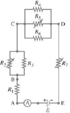
Given the circuit shown in Fig. 26–34, use the words “increases,” “decreases,” or “stays the same” to complete the following statements:
(a) If R7 increases, the potential difference between A and E _____. Assume no resistance in Ⓐ and
(b) If R7 increases, the potential difference between A and E _____. Assume Ⓐ and
(c) If R7 increases, the voltage drop across R4 __________.
(d) If R2 decreases, the current through R1 __________.
(e) If R2 decreases, the current through R6 __________.
(f) If R2 decreases, the current through R6 _____.
(g) If R5 increases, the voltage drop across R2 _____.
(h) If R5, increases, the voltage drop across R4 _____.
(i) If R2, R5, and R7 increase.
FIGURE 26–34 Question 15. R2. R5, and R7 are variable resistors (you can change their resistance), given the symbol  .
.
Want to see the full answer?
Check out a sample textbook solution
Chapter 26 Solutions
Physics for Scientists and Engineers with Modern Physics
Additional Science Textbook Solutions
College Physics: A Strategic Approach (3rd Edition)
Chemistry: An Introduction to General, Organic, and Biological Chemistry (13th Edition)
Applications and Investigations in Earth Science (9th Edition)
Microbiology: An Introduction
Campbell Biology (11th Edition)
Chemistry: A Molecular Approach (4th Edition)


- 1.62 On a training flight, a Figure P1.62 student pilot flies from Lincoln, Nebraska, to Clarinda, Iowa, next to St. Joseph, Missouri, and then to Manhattan, Kansas (Fig. P1.62). The directions are shown relative to north: 0° is north, 90° is east, 180° is south, and 270° is west. Use the method of components to find (a) the distance she has to fly from Manhattan to get back to Lincoln, and (b) the direction (relative to north) she must fly to get there. Illustrate your solutions with a vector diagram. IOWA 147 km Lincoln 85° Clarinda 106 km 167° St. Joseph NEBRASKA Manhattan 166 km 235° S KANSAS MISSOURIarrow_forwardPlz no chatgpt pls will upvotearrow_forward3.19 • Win the Prize. In a carnival booth, you can win a stuffed gi- raffe if you toss a quarter into a small dish. The dish is on a shelf above the point where the quarter leaves your hand and is a horizontal dis- tance of 2.1 m from this point (Fig. E3.19). If you toss the coin with a velocity of 6.4 m/s at an angle of 60° above the horizontal, the coin will land in the dish. Ignore air resistance. (a) What is the height of the shelf above the point where the quarter leaves your hand? (b) What is the vertical component of the velocity of the quarter just before it lands in the dish? Figure E3.19 6.4 m/s 2.1arrow_forward
- Can someone help me answer this thank you.arrow_forward1.21 A postal employee drives a delivery truck along the route shown in Fig. E1.21. Determine the magnitude and direction of the resultant displacement by drawing a scale diagram. (See also Exercise 1.28 for a different approach.) Figure E1.21 START 2.6 km 4.0 km 3.1 km STOParrow_forwardhelp because i am so lost and it should look something like the picturearrow_forward
- 3.31 A Ferris wheel with radius Figure E3.31 14.0 m is turning about a horizontal axis through its center (Fig. E3.31). The linear speed of a passenger on the rim is constant and equal to 6.00 m/s. What are the magnitude and direction of the passenger's acceleration as she passes through (a) the lowest point in her circular motion and (b) the high- est point in her circular motion? (c) How much time does it take the Ferris wheel to make one revolution?arrow_forward1.56 ⚫. Three horizontal ropes pull on a large stone stuck in the ground, producing the vector forces A, B, and C shown in Fig. P1.56. Find the magnitude and direction of a fourth force on the stone that will make the vector sum of the four forces zero. Figure P1.56 B(80.0 N) 30.0 A (100.0 N) 53.0° C (40.0 N) 30.0°arrow_forward1.39 Given two vectors A = -2.00 +3.00 +4.00 and B=3.00 +1.00 -3.00k. (a) find the magnitude of each vector; (b) use unit vectors to write an expression for the vector difference A - B; and (c) find the magnitude of the vector difference A - B. Is this the same as the magnitude of B - Ä? Explain.arrow_forward

 Principles of Physics: A Calculus-Based TextPhysicsISBN:9781133104261Author:Raymond A. Serway, John W. JewettPublisher:Cengage Learning
 College PhysicsPhysicsISBN:9781938168000Author:Paul Peter Urone, Roger HinrichsPublisher:OpenStax College
 Glencoe Physics: Principles and Problems, Student...PhysicsISBN:9780078807213Author:Paul W. ZitzewitzPublisher:Glencoe/McGraw-Hill
 Physics for Scientists and Engineers: Foundations...PhysicsISBN:9781133939146Author:Katz, Debora M.Publisher:Cengage Learning
 College PhysicsPhysicsISBN:9781305952300Author:Raymond A. Serway, Chris VuillePublisher:Cengage Learning