
Physics for Scientists and Engineers with Modern Physics
4th Edition
ISBN: 9780131495081
Author: Douglas C. Giancoli
Publisher: Addison-Wesley
expand_more
expand_more
format_list_bulleted
Videos
Textbook Question
Chapter 26, Problem 80GP
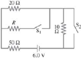
The current through the 20-Ω resistor in Fig. 26–69 does not change whether the two switches S1 and S2 are both open or both closed. Use this clue to determine the value of the unknown resistance R.
FIGURE 26–69 Problem 80.
Expert Solution & Answer
Want to see the full answer?
Check out a sample textbook solution
Students have asked these similar questions
pls help
J
K
L
The graph in the figure shows the position of an object as a function of time. The letters H-L represent
particular moments of time. At which moments shown (H, I, etc.) is the speed of the object the greatest?
+
Position
H
I
K
Time
1. Two pendula of slightly different length oscillate next to each other. The short one
oscillates with frequency 0.52 Hz and the longer one with frequency 0.50 Hz. If
they start of in phase determine their phase difference after 75 s.
Chapter 26 Solutions
Physics for Scientists and Engineers with Modern Physics
Ch. 26.1 - Repeat Example 261 assuming now that the...Ch. 26.2 - You have a 10- and a 15- resistor. What is the...Ch. 26.3 - Write the equation for the lower loop abcdefga of...Ch. 26.4 - If the jumper cables of Example 2610 were...Ch. 26.5 - In 10 times constants, the charge on the capacitor...Ch. 26 - Explain why birds can sit on power lines safely,...Ch. 26 - Discuss the advantages and disadvantages of...Ch. 26 - If all you have is a 120-V line, would it be...Ch. 26 - Two lightbulbs of resistance R1 and R2 (R2 R1)...Ch. 26 - Household outlets are often double outlets. Are...
Ch. 26 - With two identical lightbulbs and two identical...Ch. 26 - If two identical resistors are connected in series...Ch. 26 - You have a single 60-W bulb on in your room. How...Ch. 26 - When applying Kirchhoffs loop rule (such as in...Ch. 26 - Compare and discuss the formulas for resistors and...Ch. 26 - For what use are batteries connected in series?...Ch. 26 - Can the terminal voltage of a battery ever exceed...Ch. 26 - Explain in detail how you could measure the...Ch. 26 - In an RC circuit, current flows from the battery...Ch. 26 - Given the circuit shown in Fig. 2634, use the...Ch. 26 - Figure 2635 is a diagram of a capacitor (or...Ch. 26 - Design a circuit in which two different switches...Ch. 26 - What is the main difference between an analog...Ch. 26 - What would happen if you mistakenly used an...Ch. 26 - Explain why an ideal ammeter would have zero...Ch. 26 - A voltmeter connected across a resistor always...Ch. 26 - A small battery-operated flashlight requires a...Ch. 26 - Different lamps might have batteries connected in...Ch. 26 - Prob. 1PCh. 26 - (I) Four 1.50-V cells are connected in series to a...Ch. 26 - (II) A 1.5-V dry cell can be tested by connecting...Ch. 26 - (II) What is the internal resistance of a 12.0-V...Ch. 26 - (I) A 650- and a 2200- resistor are connected in...Ch. 26 - (I) Three 45- lightbulbs and three 65- lightbulbs...Ch. 26 - (I) Suppose that you have a 680-, a 720-, and a...Ch. 26 - (I) How many 10- resistors must be connected in...Ch. 26 - (II) Suppose that you have a 9.0-V battery and you...Ch. 26 - Three 1.70-k resistors can be connected together...Ch. 26 - (II) A battery with an emf of 12.0 V shows a...Ch. 26 - (II) Eight identical bulbs are connected in series...Ch. 26 - (II) Eight bulbs are connected in parallel to a...Ch. 26 - (II) The performance of the starter circuit in an...Ch. 26 - (II) A close inspection of an electric circuit...Ch. 26 - (II) Determine (a) the equivalent resistance of...Ch. 26 - (II) A 75-W, 110-V bulb is connected in parallel...Ch. 26 - (II) (a) Determine the equivalent resistance of...Ch. 26 - (II) Whal is the net resistance of the circuit...Ch. 26 - (II) Calculate the current through each resistor...Ch. 26 - (II) The two terminals of a voltage source with...Ch. 26 - (II) Two resistors when connected in series to a...Ch. 26 - (III) Three equal resistors (R) are connected to a...Ch. 26 - (III) A 2.8-k and a 3.7-k resistor are connected...Ch. 26 - (III) Consider the network of resistors shown in...Ch. 26 - (III) You are designing a wire resistance heater...Ch. 26 - (I) Calculate the current in the circuit of Fig....Ch. 26 - (II) Determine the terminal voltage of each...Ch. 26 - (II) For the circuit shown in Fig. 2647, find the...Ch. 26 - (II) (a) A network of five equal resistors R is...Ch. 26 - (II) (a) What is the potential difference between...Ch. 26 - (II) Calculate the currents in each resistor of...Ch. 26 - (II) Determine the magnitudes and directions of...Ch. 26 - (II) Determine the magnitudes and directions of...Ch. 26 - (II) A voltage V is applied to n identical...Ch. 26 - (III) (a) Determine the currents I1, I2, and I3 in...Ch. 26 - (III) What would the current I1 be in Fig. 2653 if...Ch. 26 - (III) Determine the current through each of the...Ch. 26 - (III) If the 25- resistor in Fig. 2654 is shorted...Ch. 26 - (III) Twelve resistors, each of resistance R, are...Ch. 26 - (III) Determine the net resistance in Fig. 2656...Ch. 26 - (II) Suppose two batteries, with unequal emfs of...Ch. 26 - (I) Estimate the range of resistance needed to...Ch. 26 - (II) In Fig. 2658 (same as Fig. 2617a), the total...Ch. 26 - (II) Two 3.8-F capacitors, two 2.2-k resistors,...Ch. 26 - (II) How long does it take for the energy stored...Ch. 26 - (II) A parallel-plate capacitor is filled with a...Ch. 26 - (II) The RC circuit of Fig. 2659 (same as Fig....Ch. 26 - (II) Consider the circuit shown in Fig. 2660,...Ch. 26 - (III) Determine the time constant for charging the...Ch. 26 - (III) Two resistors and two uncharged capacitors...Ch. 26 - (III) Suppose the switch S in Fig. 2662 is closed....Ch. 26 - (I) An ammeter has a sensitivity of 35,00 /V. What...Ch. 26 - (I) What is the resistance of a voltmeter on the...Ch. 26 - (II) A galvanometer has a sensitivity of 45 k/V...Ch. 26 - (II) A galvanometer has an internal resistance of...Ch. 26 - (II) A particular digital meter is based on an...Ch. 26 - (II) A milliammeter reads 25 mA full scale. It...Ch. 26 - (II) A 45-V battery of negligible internal...Ch. 26 - (II) An ammeter whose internal resistance is 53 ...Ch. 26 - (II) A battery with E=12.0V and internal...Ch. 26 - (II) A 12.0-V battery (assume the internal...Ch. 26 - (III) Two 9.4-k resistors are placed in series and...Ch. 26 - (III) When the resistor R in Fig. 2664 is 35 , the...Ch. 26 - Suppose that you wish to apply a 0.25-V potential...Ch. 26 - A three-way lightbulb can produce 50 W, 100 W, or...Ch. 26 - Suppose you want to run some apparatus that is 65...Ch. 26 - For the circuit shown in Fig. 2618a, show that the...Ch. 26 - A heart pacemaker is designed to operate at 72...Ch. 26 - Prob. 70GPCh. 26 - A Wheatstone bridge is a type of bridge circuit...Ch. 26 - An unknown length of platinum wire 1.22 mm in...Ch. 26 - The internal resistance of a 1.35-V mercury cell...Ch. 26 - How many 12-W resistors, each of the same...Ch. 26 - A solar cell, 3.0 cm square, has an output of 350...Ch. 26 - A power supply has a fixed output voltage of 12.0...Ch. 26 - The current through the 4.0-k resistor in Fig....Ch. 26 - A battery produces 40.8 V when 7.40 A is drawn...Ch. 26 - In the circuit shown in Fig. 2668, the 33-...Ch. 26 - The current through the 20- resistor in Fig. 2669...Ch. 26 - (a) A voltmeter and an ammeter can be connected as...Ch. 26 - (a) What is the equivalent resistance of the...Ch. 26 - A flashlight bulb rated at 2.0 W and 3.0 V is...Ch. 26 - Some light-dimmer switches use a variable resistor...Ch. 26 - A potentiometer is a device to precisely measure...Ch. 26 - Electronic devices often use an RC circuit to...Ch. 26 - The circuit shown in Fig. 2676 is a primitive...Ch. 26 - Determine the current in each resistor of the...Ch. 26 - In the circuit shown in Fig. 2678, switch S is...Ch. 26 - Figure 2679 shows the circuit for a simple...Ch. 26 - Measurements made on circuits that contain large...Ch. 26 - A typical voltmeter has an internal resistance of...Ch. 26 - (II) An RC series circuit contains a resistor R =...
Additional Science Textbook Solutions
Find more solutions based on key concepts
Plants use the process of photosynthesis to convert the energy in sunlight to chemical energy in the form of su...
Campbell Essential Biology (7th Edition)
12. FIGURE Q7.12 shows two masses at rest. The string is massless and the pullies are frictionless. The spring ...
Physics for Scientists and Engineers: A Strategic Approach, Vol. 1 (Chs 1-21) (4th Edition)
What are the two types of bone marrow, and what are their functions?
Human Anatomy & Physiology (2nd Edition)
Why is petroleum jelly used in the hanging-drop procedure?
Laboratory Experiments in Microbiology (12th Edition) (What's New in Microbiology)
Flower position, stem length, and seed shape are three characters that Mendel studied. Each is controlled by an...
Campbell Biology (11th Edition)
Modified True/False 3. __________ Aquatic microorganisms are more prevalent near the surface than at the bottom...
Microbiology with Diseases by Body System (5th Edition)
Knowledge Booster


Learn more about
Need a deep-dive on the concept behind this application? Look no further. Learn more about this topic, physics and related others by exploring similar questions and additional content below.Similar questions
- A mass is connect to a vertical revolving axle by two strings of length L, each making an angle of 45 degrees with the axle, as shown. Both the axle and mass are revolving with angular velocity w, Gravity is directed downward. The tension in the upper string is T_upper and the tension in the lower string is T_lower.Draw a clear free body diagram for mass m. Please include real forces only.Find the tensions in the upper and lower strings, T_upper and T_lowerarrow_forward2. A stone is dropped into a pool of water causing ripple to spread out. After 10 s the circumference of the ripple is 20 m. Calculate the velocity of the wave.arrow_forward10. Imagine you have a system in which you have 54 grams of ice. You can melt this ice and then vaporize it all at 0 C. The melting and vaporization are done reversibly into a balloon held at a pressure of 0.250 bar. Here are some facts about water you may wish to know. The density of liquid water at 0 C is 1 g/cm³. The density of ice at 0 C is 0.917 g/cm³. The enthalpy of vaporization of liquid water is 2.496 kJ/gram and the enthalpy of fusion of solid water is 333.55 J/gram. A. How much energy does the ice absorb as heat when it melts? B. How much work is involved in melting the ice? C. What is the total change in energy for melting the ice? D. What is the enthalpy change for melting the ice? E. What is the entropy change for melting the ice? F. What is the change in Helmholtz energy for melting the ice? G. What is the change in Gibbs energy for melting the ice?arrow_forward
- In the figure Q = 5.7 nC and all other quantities are accurate to 2 significant figures. What is the magnitude of the force on the charge Q? (k = 1/4πε 0 = 8.99 × 10⁹ N · m2/C2)arrow_forwardNow add a fourth charged particle, particle 3, with positive charge q3, fixed in the yz-plane at (0,d2,d2). What is the net force F→ on particle 0 due solely to this charge? Express your answer (a vector) using k, q0, q3, d2, i^, j^, and k^. Include only the force caused by particle 3.arrow_forwardFor a tornadoes and hurricanes, which of the following is most critical? an alert a watch a warning a predictionarrow_forward
- When a warm front advances up and over a cold front, what is it called? front inversion stationary front cold front occlusion warm front occlusionarrow_forward1) Consider two positively charged particles, one of charge q0 (particle 0) fixed at the origin, and another of charge q1 (particle 1) fixed on the y-axis at (0,d1,0). What is the net force F→ on particle 0 due to particle 1? Express your answer (a vector) using any or all of k, q0, q1, d1, i^, j^, and k^. 2) Now add a third, negatively charged, particle, whose charge is −q2− (particle 2). Particle 2 fixed on the y-axis at position (0,d2,0). What is the new net force on particle 0, from particle 1 and particle 2? Express your answer (a vector) using any or all of k, q0, q1, q2, d1, d2, i^, j^, and k^. 3) Particle 0 experiences a repulsion from particle 1 and an attraction toward particle 2. For certain values of d1 and d2, the repulsion and attraction should balance each other, resulting in no net force. For what ratio d1/d2 is there no net force on particle 0? Express your answer in terms of any or all of the following variables: k, q0, q1, q2.arrow_forwardA 85 turn, 10.0 cm diameter coil rotates at an angular velocity of 8.00 rad/s in a 1.35 T field, starting with the normal of the plane of the coil perpendicular to the field. Assume that the positive max emf is reached first. (a) What (in V) is the peak emf? 7.17 V (b) At what time (in s) is the peak emf first reached? 0.196 S (c) At what time (in s) is the emf first at its most negative? 0.589 x s (d) What is the period (in s) of the AC voltage output? 0.785 Sarrow_forward
- A bobsled starts at the top of a track as human runners sprint from rest and then jump into the sled. Assume they reach 40 km/h from rest after covering a distance of 50 m over flat ice. a. How much work do they do on themselves and the sled which they are pushing given the fact that there are two men of combined mass 185 kg and the sled with a mass of 200 kg? (If you haven't seen bobsledding, watch youtube to understand better what's going on.) b. After this start, the team races down the track and descends vertically by 200 m. At the finish line the sled crosses with a speed of 55 m/s. How much energy was lost to drag and friction along the way down after the men were in the sled?arrow_forwardFor what type of force is it not possible to define a potential energy expression?arrow_forward10. Imagine you have a system in which you have 54 grams of ice. You can melt this ice and then vaporize it all at 0 C. The melting and vaporization are done reversibly into a balloon held at a pressure of 0.250 bar. Here are some facts about water you may wish to know. The density of liquid water at 0 C is 1 g/cm³. The density of ice at 0 C is 0.917 g/cm³. The enthalpy of vaporization of liquid water is 2.496 kJ/gram and the enthalpy of fusion of solid water is 333.55 J/gram.arrow_forward
arrow_back_ios
SEE MORE QUESTIONS
arrow_forward_ios
Recommended textbooks for you
 Principles of Physics: A Calculus-Based TextPhysicsISBN:9781133104261Author:Raymond A. Serway, John W. JewettPublisher:Cengage Learning
 College PhysicsPhysicsISBN:9781938168000Author:Paul Peter Urone, Roger HinrichsPublisher:OpenStax College
 College PhysicsPhysicsISBN:9781305952300Author:Raymond A. Serway, Chris VuillePublisher:Cengage Learning
 College PhysicsPhysicsISBN:9781285737027Author:Raymond A. Serway, Chris VuillePublisher:Cengage Learning
 Physics for Scientists and Engineers, Technology ...PhysicsISBN:9781305116399Author:Raymond A. Serway, John W. JewettPublisher:Cengage Learning
Principles of Physics: A Calculus-Based Text
Physics
ISBN:9781133104261
Author:Raymond A. Serway, John W. Jewett
Publisher:Cengage Learning
College Physics
Physics
ISBN:9781938168000
Author:Paul Peter Urone, Roger Hinrichs
Publisher:OpenStax College
College Physics
Physics
ISBN:9781305952300
Author:Raymond A. Serway, Chris Vuille
Publisher:Cengage Learning
College Physics
Physics
ISBN:9781285737027
Author:Raymond A. Serway, Chris Vuille
Publisher:Cengage Learning
Physics for Scientists and Engineers, Technology ...
Physics
ISBN:9781305116399
Author:Raymond A. Serway, John W. Jewett
Publisher:Cengage Learning
What is Electromagnetic Induction? | Faraday's Laws and Lenz Law | iKen | iKen Edu | iKen App; Author: Iken Edu;https://www.youtube.com/watch?v=3HyORmBip-w;License: Standard YouTube License, CC-BY