Concept explainers
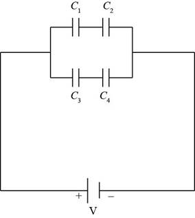
For (he system of four capacitors shown in Figure P26.19. find (a) the total energy stored in the system and (b) the energy stored by each capacitor, (c) (Compare the sum of the answers in part (b) with your result to part (a) and explain your observation.
(a)
The energy stored in the system.
Answer to Problem 26.56AP
The energy stored in the system is
Explanation of Solution
Given info: The electric potential in the system is
The Figure of the circuit diagram is shown below.

Figure (1)
Since, the capacitors
Here,
Substitute
Thus, the equivalent capacitance of the first row is
Since, the capacitors
Here,
Substitute
Thus, the equivalent capacitance of the second row is
Since, the first and second rows are in parallel to each other. So, the equivalent capacitance of the system is,
Here,
Substitute
Thus, the equivalent capacitance of the system is
Formula to calculate the energy stored in the system is,
Here,
Substitute
Conclusion:
Therefore, the energy stored in the system is
(b)
The energy stored by each capacitor.
Answer to Problem 26.56AP
The energy stored in capacitors
Explanation of Solution
Given info: The electric potential in the system is
Since, the electric potential through each capacitor is same.
Formula to calculate the charge on the first row of capacitor is,
Here,
Substitute
Thus, the charge on the first row of capacitor is
Formula to calculate the energy stored is,
Here,
The energy stored in capacitor
Here,
Substitute
Thus, the energy stored in capacitor
The energy stored in capacitor
Here,
Substitute
Thus, the energy stored in capacitor
Formula to calculate the charge on the first row of capacitor is,
Here,
Substitute
Thus, the charge on the first row of capacitor is
The energy stored in capacitor
Here,
Substitute
Thus, the energy stored in capacitor
The energy stored in capacitor
Here,
Substitute
Thus, the energy stored in capacitor
Conclusion:
Therefore, the energy stored in capacitors
(c)
The comparison of the sum of the energy in part (b) with energy of part (a) and explain it.
Answer to Problem 26.56AP
The sum of the energy of par (b) is same as the energy in part (a).
Explanation of Solution
Given info: The electric potential in the system is
The sum of the energy of the part (b) is,
Substitute
The sum of the energy of par (b) is same as the energy in part (a).
Conclusion:
Therefore, the sum of the energy of par (b) is same as the energy in part (a).
Want to see more full solutions like this?
Chapter 26 Solutions
Physics for Scientists and Engineers, Technology Update (No access codes included)
- I need help with part B. I cant seem to get the correct answer. Please walk me through what youre doing to get to the answer and what that could bearrow_forwardQuestion 6: Chlorine is widely used to purify municipal water supplies and to treat swimming pool waters. Suppose that the volume of a particular sample of Cl₂ gas is 8.70 L at 895 torr and 24°C. (a) How many grams of Cl₂ are in the sample? ⚫ Atomic mass of CI = 35.453 g/mol • Molar mass of Cl₂ = 2 x 35.453 = 70.906 g/mol Solution: Use the Ideal Gas Law: Step 1: Convert Given Values • Pressure: P = 895 torr → atm PV= = nRT 1 P = 895 × = 1.1789 atm 760 • Temperature: Convert to Kelvin: T24273.15 = 297.15 K • Gas constant: R = 0.0821 L atm/mol. K Volume: V = 8.70 L Step 2: Solve for n . PV n = RT n = (1.1789)(8.70) (0.0821)(297.15) 10.25 n = = 0.420 mol 24.405 Step 3: Calculate Mass of Cl₂ Final Answer: 29.78 g of Cl₂. mass nx M mass= (0.420)(70.906) mass= 29.78 garrow_forwardE1 R₁ w 0.50 20 Ω 12 R₁₂ ww ΒΩ R₂ 60 E3 C RA w 15 Ω E2 0.25 E4 0.75 Ω 0.5 Ωarrow_forward
- What is the force (in N) on the 2.0 μC charge placed at the center of the square shown below? (Express your answer in vector form.) 5.0 με 4.0 με 2.0 με + 1.0 m 1.0 m -40 με 2.0 μCarrow_forwardWhat is the force (in N) on the 5.4 µC charge shown below? (Express your answer in vector form.) −3.1 µC5.4 µC9.2 µC6.4 µCarrow_forwardAn ideal gas in a sealed container starts out at a pressure of 8900 N/m2 and a volume of 5.7 m3. If the gas expands to a volume of 6.3 m3 while the pressure is held constant (still at 8900 N/m2), how much work is done by the gas? Give your answer as the number of Joules.arrow_forward
 Physics for Scientists and Engineers: Foundations...PhysicsISBN:9781133939146Author:Katz, Debora M.Publisher:Cengage Learning
 Principles of Physics: A Calculus-Based TextPhysicsISBN:9781133104261Author:Raymond A. Serway, John W. JewettPublisher:Cengage Learning
 College PhysicsPhysicsISBN:9781305952300Author:Raymond A. Serway, Chris VuillePublisher:Cengage Learning
 College PhysicsPhysicsISBN:9781285737027Author:Raymond A. Serway, Chris VuillePublisher:Cengage Learning
 Physics for Scientists and Engineers, Technology ...PhysicsISBN:9781305116399Author:Raymond A. Serway, John W. JewettPublisher:Cengage Learning


