University Physics with Modern Physics Plus Mastering Physics with eText -- Access Card Package (14th Edition)
14th Edition
ISBN: 9780321982582
Author: Hugh D. Young, Roger A. Freedman
Publisher: PEARSON
expand_more
expand_more
format_list_bulleted
Videos
Textbook Question
Chapter 26, Problem 26.16DQ
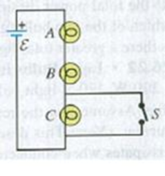
Identical light bulbs A, B, and C are connected as shown in Fig. Q26.16. When the switch S is closed, bulb C goes out. Explain why. What happens to the brightness of bulbs A and B? Explain.
Figure Q26.16
Expert Solution & Answer
Want to see the full answer?
Check out a sample textbook solution
Students have asked these similar questions
The three bulbs shown are identical. When bulb C is removed from the circuit, what happens to the brightness of bulb A? Of bulb B? Explain.
Figure shows two circuits. The two batteries are identical and the four resistors all have exactly the same resistance.a. Compare ΔVab , ΔVcd , and ΔVef . Are they all the same? If not, rank them in order from largest to smallest. Explain.b. Rank in order, from largest to smallest, the five currents I1 to I5 . Explain.
Normally, household lightbulbs are connected in parallel to a power supply.Suppose a 40 W and a 60 W lightbulb are, instead, connected in series, as shown. Which bulb is brighter?A. The 60 W bulb.B. The 40 W bulb.C. The bulbs are equally bright.
Chapter 26 Solutions
University Physics with Modern Physics Plus Mastering Physics with eText -- Access Card Package (14th Edition)
Ch. 26.1 - Suppose all three of the resistors shown in Fig....Ch. 26.2 - Subtract Eq. (1) from Eq. (2) in Example 26.6. To...Ch. 26.3 - You want to measure the current through and the...Ch. 26.4 - The energy stored in a capacitor is equal to...Ch. 26.5 - To prevent the circuit breaker in Example 26.14...Ch. 26 - In which 120-V light bulb does the filament have...Ch. 26 - Two 120-V light bulbs, one 25-W and one 200-W,...Ch. 26 - You connect a number of identical light bulbs to a...Ch. 26 - In the circuit shown in Fig. Q26.4, three...Ch. 26 - If two resistors R1 and R2 (R2 R1) are connected...
Ch. 26 - If two resistors R1 and R2 (R2 R1) are connected...Ch. 26 - A battery with no internal resistance is connected...Ch. 26 - A resistor consists of three identical metal...Ch. 26 - A light bulb is connected in the circuit shown in...Ch. 26 - A real battery, having nonnegligible internal...Ch. 26 - If the battery in Discussion Question Q26.10 is...Ch. 26 - Consider the circuit shown in Fig. Q26.12. What...Ch. 26 - Is it possible to connect resistors together in a...Ch. 26 - The battery in the circuit shown in Fig. Q26.14...Ch. 26 - In a two-cell flashlight, the batteries are...Ch. 26 - Identical light bulbs A, B, and C are connected as...Ch. 26 - The emf of a flashlight battery is roughly...Ch. 26 - Will the capacitors in the circuits shown in Fig....Ch. 26 - Verify that the time constant RC has units of...Ch. 26 - For very large resistances it is easy to construct...Ch. 26 - When a capacitor, battery, and resistor are...Ch. 26 - A uniform wire of resistance R is cut into three...Ch. 26 - A machine part has a resistor X protruding from an...Ch. 26 - A resistor with R1 = 25.0 is connected to a...Ch. 26 - A 42- resistor and a 20- resistor are connected in...Ch. 26 - A triangular array of resistors is shown in Fig....Ch. 26 - For the circuit shown in Fig. E26.6 both meters...Ch. 26 - For the circuit shown in Fig. E26.7 find the...Ch. 26 - Three resistors having resistances of 1.60 , 2.40...Ch. 26 - Now the three resistors of Exercise 26.8 are...Ch. 26 - Power Rating of a Resistor. The power rating of a...Ch. 26 - In Fig. E26.11, R1, = 3.00 , R2 = 6.00 , and R3=...Ch. 26 - In Fig. E26.11 the battery has emf 35.0 V and...Ch. 26 - Compute the equivalent resistance of the network...Ch. 26 - Compute the equivalent resistance of the network...Ch. 26 - In the circuit of Fig. E26.15, each resistor...Ch. 26 - Consider the circuit shown in Fig. E26.16. The...Ch. 26 - In the circuit shown in Fig. E26.17, the voltage...Ch. 26 - In the circuit shown in Fig. E26.18, = 36.0 V,...Ch. 26 - CP In the circuit in Fig. E26.19, a 20.0- resistor...Ch. 26 - In the circuit shown in Fig. E26.20, the rate at...Ch. 26 - Light Bulbs in Series and in Parallel. Two light...Ch. 26 - Light Bulbs in Series. A 60-W, 120-V light bulb...Ch. 26 - In the circuit shown in Fig. E26.23, ammeter A1...Ch. 26 - The batteries shown in the circuit in Fig. E26.24...Ch. 26 - In the circuit shown in Fig. E26.25 find (a) the...Ch. 26 - Find the emfs 1 and 2 in the circuit of Fig....Ch. 26 - In the circuit shown in Fig. E26.27, find (a) the...Ch. 26 - In the circuit shown in Fig. E26.28, find (a) the...Ch. 26 - The 10.00-V battery in Fig. E26.28 is removed from...Ch. 26 - The 5.00-V battery in Fig. E26.28 is removed from...Ch. 26 - In the circuit shown in Fig. E26.31 the batteries...Ch. 26 - In the circuit shown in Fig. E26.32 both batteries...Ch. 26 - In the circuit shown in Fig. E26.33 all meters are...Ch. 26 - In the circuit shown in Fig. E26.34, the 6.0-...Ch. 26 - The resistance of a galvanometer coil is 25.0 ,...Ch. 26 - The resistance of the coil of a pivoted coil...Ch. 26 - A circuit consists of a series combination of...Ch. 26 - A galvanometer having a resistance of 25.0 has a...Ch. 26 - A capacitor is charged to a potential of 12.0 V...Ch. 26 - You connect a battery, resistor, and capacitor as...Ch. 26 - A 4.60-F capacitor that is initially uncharged is...Ch. 26 - You connect a battery, resistor, and capacitor as...Ch. 26 - CP In the circuit shown in Fig. E26.43 both...Ch. 26 - A 12.4-F capacitor is connected through a 0.895-M...Ch. 26 - An emf source with = 120 V, a resistor with R =...Ch. 26 - A resistor and a capacitor are connected in series...Ch. 26 - CP In the circuit shown in Fig. E26.47 each...Ch. 26 - A 1.50-F capacitor is charging through a 12.0-...Ch. 26 - In the circuit in Fig. E26.49 the capacitors are...Ch. 26 - A 12.0-F capacitor is charged to a potential of...Ch. 26 - In the circuit shown in Fig. E26.51, C = 5.90 F, ...Ch. 26 - Prob. 26.52ECh. 26 - A 1500-W electric beater is plugged into the...Ch. 26 - In Fig. P26.54, the battery has negligible...Ch. 26 - The two identical light bulbs in Example 26.2...Ch. 26 - Each of the three resistors in Fig. P26.56 has a...Ch. 26 - (a) Find the potential of point a with respect to...Ch. 26 - CP For the circuit shown in Fig. P26.58 a 20.0-...Ch. 26 - Calculate the three currents I1, I2, and I3...Ch. 26 - What must the emf in Fig. P26.60 be in order for...Ch. 26 - Find the current through each of the three...Ch. 26 - (a) Find the current through the battery and each...Ch. 26 - Consider the circuit shown in Fig. P26.63. (a)...Ch. 26 - In the circuit shown in Fig. P26.64, = 24.0 V,...Ch. 26 - In the circuit shown in Fig. P26.65, the current...Ch. 26 - In the circuit shown in Fig. P26.66 all the...Ch. 26 - Figure P26.67 employs a convention often used in...Ch. 26 - Three identical resistors are connected in series....Ch. 26 - A resistor R1 consumes electrical power P1 when...Ch. 26 - The capacitor in Fig. F26.70 is initially...Ch. 26 - A 2.00-F capacitor that is initially uncharged is...Ch. 26 - A 6.00-F capacitor that is initially uncharged is...Ch. 26 - Point a in Fig. P26.73 is maintained at a constant...Ch. 26 - The Wheatstone Bridge. The circuit shown in Fig....Ch. 26 - (See Problem 26.67.) (a) What is the potential of...Ch. 26 - A 2.36-F capacitor that is initially uncharged is...Ch. 26 - A 224- resistor and a 589- resistor are connected...Ch. 26 - A resistor with R = 850 is connected to the...Ch. 26 - A capacitor that is initially uncharged is...Ch. 26 - DATA You set up the circuit shown in Fig. 26.22a,...Ch. 26 - DATA You set up the circuit shown in Fig. 26.20....Ch. 26 - DATA The electronics supply company where you work...Ch. 26 - An Infinite Network. As shown in Fig. P26.83, a...Ch. 26 - Suppose a resistor R lies along each edge of a...Ch. 26 - BIO Attenuator Chains and Axons. The infinite...Ch. 26 - Assume that a typical open ion channel spanning an...Ch. 26 - In a simple model of an axon conducting a nerve...Ch. 26 - Cell membranes across a wide variety of organisms...
Additional Science Textbook Solutions
Find more solutions based on key concepts
When the momentum of an object or system of objects does not change with time, the momentum of the object or sy...
Tutorials in Introductory Physics
A 240-V electric motor is 90% efficient, meaning that 90% of the energy supplied to it ends up as mechanical wo...
Essential University Physics: Volume 2 (3rd Edition)
The two circuits shown below act as crude low-pass filters. The input voltage to the circuits is vin, and the o...
University Physics Volume 2
To compute the specific heat of a metal.
Glencoe Physical Science 2012 Student Edition (Glencoe Science) (McGraw-Hill Education)
34. Find the maximum possible coefficient of performance for a heat pump used to heat a house in a northerly cl...
College Physics: A Strategic Approach (3rd Edition)
Looking for signals from star systems is a poor approach, because any truly advanced civilization will have mov...
Life in the Universe (4th Edition)
Knowledge Booster


Learn more about
Need a deep-dive on the concept behind this application? Look no further. Learn more about this topic, physics and related others by exploring similar questions and additional content below.Similar questions
- The- pair of capacitors in Figure P28.63 are fully charged by a 12.0-V battery. The battery is disconnected, and the switch is then closed. Alter 1.00 ms has elapsed, (a) how much charge remains 011 the 3.00-F capacitor? (b) How much charge remains on the 2.00-F capacitor? (c) What is the current in the resistor at this time?arrow_forwardAn uncharged capacitor with C=43μF and a resistor with R=75Ω are connected in series with a battery of ϵ=7.5 V. a. Express the time constant τ in terms of R and C. b. Calculate the numerical value of τ in microseconds. c. Express the maximum charge Q on the capacitor in terms of C and ϵ. d. Calculate the numerical value of Q in microcoulombs.arrow_forwardThe four bulbs shown are identical. Rank the bulbs from brightest to dimmest. Explain.arrow_forward
- = The circuit in the figure below contains two resistors, R₁ 5.00k and R₂ 6.00k, and two capacitors, C₁ = 5.00uF and C₂ = 6.00uF, connected to a battery with emf E = 110V. If no charges exist on the capacitors before switch S is closed, determine the charge 9₁ on capacitor C₁ 1.00ms after the switch is closed. R₁ C₁ de b с www R₂ S afor C₂ E Determine the charge 92 on capacitor C₂ 1.00ms after the switch is closed.arrow_forwardThe circuit in Figure P27.41 contains two resistors, R1 = 2.00 kΩ and R2 = 3.00 kΩ, and two capacitors, C1 = 2.00 μF and C2 = 3.00 μF, connected to a battery with emf ε = 120 V. If there are no charges on the capacitors before switch S is closed, determine the charges on capacitors (a) C1 and (b) C2 as functions of time, after the switch is closed.arrow_forwardPlease Asaparrow_forward
- 5. A 6.00 uf capacitor with an initial charge of 1200 µC is discharged through a 4.0 M2 resistor. a) Calculate the magnitude of the current in the resistor 12.0 s after the resistor is connected across the terminals of the capacitor. VC = (1- e24) %3D 4E6 1.2NO -10 b) What is the charge that remains on the capacitor after 12.0s? 2=Q (1-e-Tha 1/241 T-24 See 2=4.7 x10- %3D c) How much energy has the capacitor dissipated through the resistor in those 12 s? (Hint: energy is the integral of the power with respect to time.) 12 8.31 xio4 12arrow_forwardAn ammeter is (incorrectly) inserted into a circuit as shown.a. What is the current through the 5.0 Ω resistor?b. How would you change the circuit to correctly connect the ammeter to measure the current through the 5.0 Ω resistor?arrow_forward3. The circuit in Figure P28.75 contains two resistors, R1 = 2.00 k2 and R2 = 3.00 kN, and two capacitors, C = 2.00 µF and C2 = 3.00 µF, connected to a battery with emf ɛ = 120 V. No charge is on either capacitor before switch S is closed. Determine the charges q1 and q2 on capacitors C1 and C2, respectively, after the switch is closed. (Suggestion: First reconstruct the circuit so that it becomes a simple RC circuit containing a single resistor and single capacitor in series, connected to the battery, and then deter- mine the total charge qstored in the equivalent circuit.) %3D %3D %3D R1 R2 C2 S Figure P28.75arrow_forward
- A capacitor with a capacitance of 3.5 μF is initially uncharged. It is connected in series with a switch of negligible resistance, a resistor with a resistance of 19 kΩ, and a battery that has a potential difference of 170 V. a. Immediately after the switch is closed, what is the voltage drop VC, in volts, across the capacitor? b. Immediately after the switch is closed, what is the voltage drop VR, in volts, across the resistor? c. Immediately after the switch is closed, what is the current, in amperes, through the resistor? d. Find an expression for the time after the switch is closed when the current in the resistor equals half its maximum value. e. What is the charge Q, in microcoulombs, on the capacitor when the current in the resistor equals one half its maximum value.arrow_forward3. A 30µF capacitor is connected in series to a 1000 resistor. Initially the capacitor is not charged. At time = Os they are connected in series to a 36V battery. What is the voltage across the capacitor after 2.5ms? a. b. What is the maximum charge on the capacitor as t>∞? C. The capacitor is completely charged and the battery disconnected. The resistor is connected in series with the charged capacitor. How long does it take for 85% of the capacitor's charge to discharge through the resistor?arrow_forward2o2 3052 352 552 652 2A A. The power dissipated in the 3 Ohms resistor is W. B. The total voltage is V. C. The power dissipated in the 5 Ohms resistor is W. Round all answers to whole numbers.arrow_forward
arrow_back_ios
SEE MORE QUESTIONS
arrow_forward_ios
Recommended textbooks for you
 Physics for Scientists and Engineers: Foundations...PhysicsISBN:9781133939146Author:Katz, Debora M.Publisher:Cengage Learning
 Physics for Scientists and Engineers, Technology ...PhysicsISBN:9781305116399Author:Raymond A. Serway, John W. JewettPublisher:Cengage Learning
 Physics for Scientists and EngineersPhysicsISBN:9781337553278Author:Raymond A. Serway, John W. JewettPublisher:Cengage Learning
 Physics for Scientists and Engineers with Modern ...PhysicsISBN:9781337553292Author:Raymond A. Serway, John W. JewettPublisher:Cengage Learning
 Principles of Physics: A Calculus-Based TextPhysicsISBN:9781133104261Author:Raymond A. Serway, John W. JewettPublisher:Cengage Learning
Physics for Scientists and Engineers: Foundations...
Physics
ISBN:9781133939146
Author:Katz, Debora M.
Publisher:Cengage Learning
Physics for Scientists and Engineers, Technology ...
Physics
ISBN:9781305116399
Author:Raymond A. Serway, John W. Jewett
Publisher:Cengage Learning
Physics for Scientists and Engineers
Physics
ISBN:9781337553278
Author:Raymond A. Serway, John W. Jewett
Publisher:Cengage Learning
Physics for Scientists and Engineers with Modern ...
Physics
ISBN:9781337553292
Author:Raymond A. Serway, John W. Jewett
Publisher:Cengage Learning
Principles of Physics: A Calculus-Based Text
Physics
ISBN:9781133104261
Author:Raymond A. Serway, John W. Jewett
Publisher:Cengage Learning
How To Solve Any Resistors In Series and Parallel Combination Circuit Problems in Physics; Author: The Organic Chemistry Tutor;https://www.youtube.com/watch?v=eFlJy0cPbsY;License: Standard YouTube License, CC-BY