University Physics with Modern Physics Plus Mastering Physics with eText -- Access Card Package (14th Edition)
14th Edition
ISBN: 9780321982582
Author: Hugh D. Young, Roger A. Freedman
Publisher: PEARSON
expand_more
expand_more
format_list_bulleted
Videos
Textbook Question
Chapter 26, Problem 26.60P
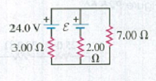
What must the emf ε in Fig. P26.60 be in order for the current through the 7.00-Ω resistor to be 1.80 A? Each emf source has negligible internal resistance.
Figure P26.60
Expert Solution & Answer

Learn your wayIncludes step-by-step video

schedule07:01
Students have asked these similar questions
25.54. In the circuit shown in
Fig. P25.54, R is a variable resistor whose
value ranges from 0 to co, and a and b are
the terminals of a battery that has an emf
E = 15.0V and an internal resistance of
4.00 2. The ammeter and voltmeter are
idealized meters. As R varies over its full
range of values, what will be the largest
and smallest readings of (a) the voltmeter
and (b) the ammeter? (c) Sketch qualita-
tive graphs of the readings of both meters
as functions of R.
Figure P25.54
R
The figure shows a simple RC circuit consisting of a 100.0-V battery in series with a 10.0-µF capacitor and a resistor. Initially, the
switch S is open and the capacitor is uncharged. Two seconds after the switch is closed, the voltage across the resistor is 37 V.
R
S
www
100.0 V
T
3
0.0.37 Ω
O 2.0 × 10⁵Q
Ο 2.70 Ω
O 4.3 × 10⁵Q
O 5.0 × 10⁴Q
10.0 uF
Determine the numerical value of the resistance R.
A charging RC circuit controls the intermittent windshield wipers in a car. The emf is 12.0 V. The wipers are triggered when the voltage across the 110 μF capacitor reaches 10.0 V; then the capacitor is quickly discharged (through a much smaller resistor) and the cycle repeats. What resistance should be used in the charging circuit if the wipers are to operate once every 1.40 s?
Chapter 26 Solutions
University Physics with Modern Physics Plus Mastering Physics with eText -- Access Card Package (14th Edition)
Ch. 26.1 - Suppose all three of the resistors shown in Fig....Ch. 26.2 - Subtract Eq. (1) from Eq. (2) in Example 26.6. To...Ch. 26.3 - You want to measure the current through and the...Ch. 26.4 - The energy stored in a capacitor is equal to...Ch. 26.5 - To prevent the circuit breaker in Example 26.14...Ch. 26 - In which 120-V light bulb does the filament have...Ch. 26 - Two 120-V light bulbs, one 25-W and one 200-W,...Ch. 26 - You connect a number of identical light bulbs to a...Ch. 26 - In the circuit shown in Fig. Q26.4, three...Ch. 26 - If two resistors R1 and R2 (R2 R1) are connected...
Ch. 26 - If two resistors R1 and R2 (R2 R1) are connected...Ch. 26 - A battery with no internal resistance is connected...Ch. 26 - A resistor consists of three identical metal...Ch. 26 - A light bulb is connected in the circuit shown in...Ch. 26 - A real battery, having nonnegligible internal...Ch. 26 - If the battery in Discussion Question Q26.10 is...Ch. 26 - Consider the circuit shown in Fig. Q26.12. What...Ch. 26 - Is it possible to connect resistors together in a...Ch. 26 - The battery in the circuit shown in Fig. Q26.14...Ch. 26 - In a two-cell flashlight, the batteries are...Ch. 26 - Identical light bulbs A, B, and C are connected as...Ch. 26 - The emf of a flashlight battery is roughly...Ch. 26 - Will the capacitors in the circuits shown in Fig....Ch. 26 - Verify that the time constant RC has units of...Ch. 26 - For very large resistances it is easy to construct...Ch. 26 - When a capacitor, battery, and resistor are...Ch. 26 - A uniform wire of resistance R is cut into three...Ch. 26 - A machine part has a resistor X protruding from an...Ch. 26 - A resistor with R1 = 25.0 is connected to a...Ch. 26 - A 42- resistor and a 20- resistor are connected in...Ch. 26 - A triangular array of resistors is shown in Fig....Ch. 26 - For the circuit shown in Fig. E26.6 both meters...Ch. 26 - For the circuit shown in Fig. E26.7 find the...Ch. 26 - Three resistors having resistances of 1.60 , 2.40...Ch. 26 - Now the three resistors of Exercise 26.8 are...Ch. 26 - Power Rating of a Resistor. The power rating of a...Ch. 26 - In Fig. E26.11, R1, = 3.00 , R2 = 6.00 , and R3=...Ch. 26 - In Fig. E26.11 the battery has emf 35.0 V and...Ch. 26 - Compute the equivalent resistance of the network...Ch. 26 - Compute the equivalent resistance of the network...Ch. 26 - In the circuit of Fig. E26.15, each resistor...Ch. 26 - Consider the circuit shown in Fig. E26.16. The...Ch. 26 - In the circuit shown in Fig. E26.17, the voltage...Ch. 26 - In the circuit shown in Fig. E26.18, = 36.0 V,...Ch. 26 - CP In the circuit in Fig. E26.19, a 20.0- resistor...Ch. 26 - In the circuit shown in Fig. E26.20, the rate at...Ch. 26 - Light Bulbs in Series and in Parallel. Two light...Ch. 26 - Light Bulbs in Series. A 60-W, 120-V light bulb...Ch. 26 - In the circuit shown in Fig. E26.23, ammeter A1...Ch. 26 - The batteries shown in the circuit in Fig. E26.24...Ch. 26 - In the circuit shown in Fig. E26.25 find (a) the...Ch. 26 - Find the emfs 1 and 2 in the circuit of Fig....Ch. 26 - In the circuit shown in Fig. E26.27, find (a) the...Ch. 26 - In the circuit shown in Fig. E26.28, find (a) the...Ch. 26 - The 10.00-V battery in Fig. E26.28 is removed from...Ch. 26 - The 5.00-V battery in Fig. E26.28 is removed from...Ch. 26 - In the circuit shown in Fig. E26.31 the batteries...Ch. 26 - In the circuit shown in Fig. E26.32 both batteries...Ch. 26 - In the circuit shown in Fig. E26.33 all meters are...Ch. 26 - In the circuit shown in Fig. E26.34, the 6.0-...Ch. 26 - The resistance of a galvanometer coil is 25.0 ,...Ch. 26 - The resistance of the coil of a pivoted coil...Ch. 26 - A circuit consists of a series combination of...Ch. 26 - A galvanometer having a resistance of 25.0 has a...Ch. 26 - A capacitor is charged to a potential of 12.0 V...Ch. 26 - You connect a battery, resistor, and capacitor as...Ch. 26 - A 4.60-F capacitor that is initially uncharged is...Ch. 26 - You connect a battery, resistor, and capacitor as...Ch. 26 - CP In the circuit shown in Fig. E26.43 both...Ch. 26 - A 12.4-F capacitor is connected through a 0.895-M...Ch. 26 - An emf source with = 120 V, a resistor with R =...Ch. 26 - A resistor and a capacitor are connected in series...Ch. 26 - CP In the circuit shown in Fig. E26.47 each...Ch. 26 - A 1.50-F capacitor is charging through a 12.0-...Ch. 26 - In the circuit in Fig. E26.49 the capacitors are...Ch. 26 - A 12.0-F capacitor is charged to a potential of...Ch. 26 - In the circuit shown in Fig. E26.51, C = 5.90 F, ...Ch. 26 - Prob. 26.52ECh. 26 - A 1500-W electric beater is plugged into the...Ch. 26 - In Fig. P26.54, the battery has negligible...Ch. 26 - The two identical light bulbs in Example 26.2...Ch. 26 - Each of the three resistors in Fig. P26.56 has a...Ch. 26 - (a) Find the potential of point a with respect to...Ch. 26 - CP For the circuit shown in Fig. P26.58 a 20.0-...Ch. 26 - Calculate the three currents I1, I2, and I3...Ch. 26 - What must the emf in Fig. P26.60 be in order for...Ch. 26 - Find the current through each of the three...Ch. 26 - (a) Find the current through the battery and each...Ch. 26 - Consider the circuit shown in Fig. P26.63. (a)...Ch. 26 - In the circuit shown in Fig. P26.64, = 24.0 V,...Ch. 26 - In the circuit shown in Fig. P26.65, the current...Ch. 26 - In the circuit shown in Fig. P26.66 all the...Ch. 26 - Figure P26.67 employs a convention often used in...Ch. 26 - Three identical resistors are connected in series....Ch. 26 - A resistor R1 consumes electrical power P1 when...Ch. 26 - The capacitor in Fig. F26.70 is initially...Ch. 26 - A 2.00-F capacitor that is initially uncharged is...Ch. 26 - A 6.00-F capacitor that is initially uncharged is...Ch. 26 - Point a in Fig. P26.73 is maintained at a constant...Ch. 26 - The Wheatstone Bridge. The circuit shown in Fig....Ch. 26 - (See Problem 26.67.) (a) What is the potential of...Ch. 26 - A 2.36-F capacitor that is initially uncharged is...Ch. 26 - A 224- resistor and a 589- resistor are connected...Ch. 26 - A resistor with R = 850 is connected to the...Ch. 26 - A capacitor that is initially uncharged is...Ch. 26 - DATA You set up the circuit shown in Fig. 26.22a,...Ch. 26 - DATA You set up the circuit shown in Fig. 26.20....Ch. 26 - DATA The electronics supply company where you work...Ch. 26 - An Infinite Network. As shown in Fig. P26.83, a...Ch. 26 - Suppose a resistor R lies along each edge of a...Ch. 26 - BIO Attenuator Chains and Axons. The infinite...Ch. 26 - Assume that a typical open ion channel spanning an...Ch. 26 - In a simple model of an axon conducting a nerve...Ch. 26 - Cell membranes across a wide variety of organisms...
Additional Science Textbook Solutions
Find more solutions based on key concepts
The order of each of the overlapping lines.
Physics (5th Edition)
During a hailstorm, hailstones with an average mass of 2 g and a speed of 15 m/s strike a window pane at 45 ang...
An Introduction to Thermal Physics
42. (II) A box is given a push so that it slides across the floor. How far will it go, given that the coefficie...
Physics: Principles with Applications
Give the metric prefix fir each value:
1. 1000
Applied Physics (11th Edition)
What class of motion, natural or violent, did Aristotle attribute to motion of the Moon?
Conceptual Physics (12th Edition)
You allow 40 min to drive 25 mi to the airport, but youre caught in heavy traffic and average only 20 mi/h for ...
Essential University Physics: Volume 1 (3rd Edition)
Knowledge Booster


Learn more about
Need a deep-dive on the concept behind this application? Look no further. Learn more about this topic, physics and related others by exploring similar questions and additional content below.Similar questions
- SN 10. A 11.0 μF capacitor is connected in series to a 50.0-V battery, a is flowing through the resistor, 5.00 ms after closing the switch? Amp resistor, and a switch. What is the current that 550-52 resis 0 ssf60 ssf60 ss. 50 ssf60arrow_forwardWhat are the expected readings of the ammeter and voltmeterfor the circuit in Figure P18.65?arrow_forwardA series circuit is comprised of a 200VDC battery, a switch, a 1 kΩ resistor and a 10000 µF capacitor. Initially the switch is open and the capacitor is uncharged. What is the resistor voltage 29 seconds after the switch is closed? answer should be in V.arrow_forward
- 25.33 The circuit shown Figure E25.33 in Fig. E25.33 contains two batteries, each with an emf and an internal resistance, and two resistors. Find (a) the current in 5.0 N the circuit (magnitude and di- rection) and (b) theterminal volt- 1.6 Ω 16.0V ww b. a 90 Ω 1.4 N 8.0V ww age Vab of the 16.0-V battery.arrow_forwardThe current through the 30 Ω resistor shown is measured to be 0.25 A. What is the emf ε of the battery?arrow_forwardSwitch S in in the figure is closed at time t = 0, to begin charging an initially uncharged capacitor of capacitance C = 17.9 µF through a resistor of resistance R = 22.8 2. At what time is the potential across the capacitor equal to that across the resistor? Number i 0 Units H S W m R ◄► сarrow_forward
- 31. For the circuit shown in Fig- ure P23.31, find the current through and the potential differ- ence across each resistor. Place your results in a table for ease of reading. FIGURE P23.31 6.0 Ω 24 V www 6.0 Ω 15 Ω 4.0 Ω wwarrow_forwardA battery has emf E and internal resistance r = 2.00 Ω. A 12.0 Ω resistor is connected to the battery, and the resistor consumes electrical power at a rate of 96.0 J/ What is the emf of the battery?arrow_forwardFigure E26.26 2.00 210.00 V a ww 1.00 2 5.00 V www 10.00 Ω ww 26.27 The 10.00 V battery in Fig. E26.26 is removed from the cir- cuit and reinserted with the opposite polarity, so that its positive ter- minal is now next to point a. The rest of the circuit is as shown in the figure. Find (a) the current in each branch and (b) the potential differ- ence Van of point a relative to point b. 3.00 Ω 4.00 Ω barrow_forward
- What is the equivalent resistance of each group of resistors shown?arrow_forwardTopic: Kirchhoff’s Rules Find the emfs and in the circuit of Fig. E26.26, and find the potential difference of point b relative to point a.arrow_forwardThe figure below shows a simple RC circuit with a 2.90-μF capacitor, a 2.80-MQ resistor, a 9.00-V emf, and a switch. What are the following exactly 9.00 s after the switch is closed? S E + (a) the charge on the capacitor HC (b) the current in the resistor μA www R (c) the rate at which the capacitor is storing energy μW (d) the rate at which the battery is delivering energy μWarrow_forward
arrow_back_ios
SEE MORE QUESTIONS
arrow_forward_ios
Recommended textbooks for you
 Principles of Physics: A Calculus-Based TextPhysicsISBN:9781133104261Author:Raymond A. Serway, John W. JewettPublisher:Cengage Learning
 Physics for Scientists and Engineers: Foundations...PhysicsISBN:9781133939146Author:Katz, Debora M.Publisher:Cengage Learning
Principles of Physics: A Calculus-Based Text
Physics
ISBN:9781133104261
Author:Raymond A. Serway, John W. Jewett
Publisher:Cengage Learning
Physics for Scientists and Engineers: Foundations...
Physics
ISBN:9781133939146
Author:Katz, Debora M.
Publisher:Cengage Learning
DC Series circuits explained - The basics working principle; Author: The Engineering Mindset;https://www.youtube.com/watch?v=VV6tZ3Aqfuc;License: Standard YouTube License, CC-BY