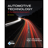
Automotive Technology: A Systems Approach (MindTap Course List)
6th Edition
ISBN: 9781133612315
Author: Jack Erjavec, Rob Thompson
Publisher: Cengage Learning
expand_more
expand_more
format_list_bulleted
Concept explainers
Textbook Question
Chapter 25, Problem 9RQ
Many control systems have operating modes that can be accessed with a scan tool to control the operation of an output. What are the names of the two most common modes for controlling outputs?
Expert Solution & Answer
Trending nowThis is a popular solution!

Students have asked these similar questions
Methylamine is used in the manufacturing of several various pharmaceutical products. Atone facility, there is a 2000 lbm tank of methylamine. If the entire tank is releasedcontinuously during a 20-minute time period, determine the concentration in ppm at adistance 1 mile directly downwind. Does this exceed published exposure limits formethylamine? Assume the release is at ground level, and it is an overcast night with a 5mph wind.
Emergency response for the rupture of an ammonia pipeline is being planned. Themaximum estimated flow rate from the rupture is 20 kg/s. Local authorities havedetermined that evacuations are necessary if the concentration exceeds the ERPG-2 level.Assume a temperature of 20˚C, wind speed of 3 m/s, atmospheric pressure of 1 atm, 70%cloud cover and rural conditions. State any other assumptions.a. How far directly downwind needs to be evacuated?b. Using a spreadsheet (such as excel), draw a plot of the isopleth at thisconcentration. You should have at least 8 different distances downwind markedon your plot.
A reactor in a pesticide plant contains 8000 lbm of a liquid mixture of 50% by weightmethyl isocyanate (MIC). The liquid is near its boiling point. A study of various releasescenarios indicates that a rupture of the reactor will spill the liquid to a boiling pool onthe ground. The boiling rate of the MIC has been estimated to be 50 lb m/min. Evacuationof the population must occur in areas where the vapor concentration exceeds ERPG-3levels. If the wind speed is 10 mph on a clear winter night, estimate the distancedownwind that must be evacuated.
Chapter 25 Solutions
Automotive Technology: A Systems Approach (MindTap Course List)
Ch. 25 - OBD II systems use several modes of operation....Ch. 25 - List the four ways that individual components can...Ch. 25 - True or False? A bad ground can cause an increase...Ch. 25 - True or False? An A/F ratio sensor can be tested...Ch. 25 - A typical normal oxygen sensor signal will toggle...Ch. 25 - Prob. 6RQCh. 25 - When an engine is running lean, the voltage signal...Ch. 25 - List six steps involved in performing a visual...Ch. 25 - Many control systems have operating modes that can...Ch. 25 - Which of the following statements about zirconium...
Ch. 25 - Describe the typical procedure for adjusting a TP...Ch. 25 - Why does the rotor for a CKP have one or more...Ch. 25 - A system may fail the catalyst monitor test for...Ch. 25 - A defective LAT sensor or circuit may cause the...Ch. 25 - Which of the following is the least likely cause...Ch. 25 - Technician A says that an oxygen sensor can be a...Ch. 25 - Prob. 2ASRQCh. 25 - While discussing ECT sensor diagnosis: Technician...Ch. 25 - While discussing Hall-effect vehicle speed sensor...Ch. 25 - While discussing TP sensor diagnosis: Technician A...Ch. 25 - While diagnosing the cause of a hard starting...Ch. 25 - While discussing testing OBD II system components:...Ch. 25 - When testing a frequency varying MAF: Technician A...Ch. 25 - Technician A says that a faulty MAF sensor can...Ch. 25 - While discussing the MIL on OBD 11 systems:...
Knowledge Booster
Learn more about
Need a deep-dive on the concept behind this application? Look no further. Learn more about this topic, mechanical-engineering and related others by exploring similar questions and additional content below.Similar questions
- A burning dump emits an estimated 1.5 kg/min of nitrogen dioxide (NO2 ). On a partlycloudy morning with a 2.5 m/s wind and temperature of 18°C, what is the concentrationof NO2 at a distance of 3.0 km directly downwind of the dump? Does this exceed theshort-term exposure limit for NO2 ? State your assumptions.arrow_forwardFor each set of measurements below, calculate the Grubbs statistic, G, look up the appropriate critical value of G from Table 4.6, and determine whether the Grubbs test supports discarding the first value in the list at the 95% level of confidence. a) 106.0, 165.0, 167.5, 170.5, 163.5, 170.7 (Geale -2.028; Gerit 1.822; yes, the Grubbs test supports discarding 106.0) b) 214.8, 263.0, 229.9, 236.9, 221.8, 230.8, 241.1 c) 357.0, 309.3, 304.9, 314.8, 305.8, 295.3, 284.7, 299.5 TABLE 4-6 Critical values of G for rejection of outlier Number of observations otsulsve os Tenos nagsibarito G to buboxy (95% confidence) 456 1.463 1.672 1.822 7 1.938 8 upa 2.032 9 2.110 10 2.176 - 1 12 15 20 11 2.234 2.285 2.409 2.557arrow_forward#1 A irreversible isothermal gas-phase isomerization reaction is given as: AB. This reaction is conducted in a 400L batch reactor and 100 mol of A (NAD = 100 mol) is charged into this reactor. The rate of reaction is determined as a function of the conversion of reactant A and the results are given below. The temperature was constant at 500K and the total pressure was constant at 830 kPa. The entering number of moles of species A is 100 mol. Calculate the time necessary to achieve 80% conversion. 0 0.1 0.2 0.4 -TA (mol/m³.s) 0.45 0.37 0.3 0.195 0.6 0.113 0.7 0.079 0.8 0.05arrow_forward
- #3 A irreversible isothermal liquid-phase reaction is given as: A → B is conducted in continuous flow systems. The rate of reaction is determined as a function of the conversion of reactant A and the results are given below. The temperature was constant at 500K. The entering molar flow rate of A is 0.4 mol/min. a) If this reaction is conducted in two CSTRS in series. Calculate the required reactor volume of each CSTRS if conversion X₁ = 0.4 and conversion X2 = 0.8. b) If this reaction is conducted in two PFRS in series. Calculate the required reactor volume of each PFRS if conversion X₁ = 0.4 and conversion X2 = 0.8. c) If this reaction is conducted in a PFR followed by a CSTR. Calculate the required reactor volume of PFR if conversion X₁ = 0.4 and of CSTR if conversion X2 = 0.8. X -A (mol/L.min) 0 0.1 0.2 0.4 0.6 0.7 0.8 0.45 0.37 0.3 0.195 0.113 0.079 0.05arrow_forward#2 An exothermic reaction, AB + C, was carried out adiabatically in a PFR or a CSTR and the following data was recorded. The entering molar flow rate of A was 300 mol/min. Calculate the necessary i) PFR volume and ii) CSTR volume to achieve 40% conversion. X 0 0.2 0.4 0.45 0.5 0.6 0.8 0.9 -TA (mol/L-min) 1 1.67 5 5 5 5 1.25 0.91arrow_forwardQuestion: McDaniel Shipyards wants to develop control charts to assess the quality of its steel plate. They... McDaniel Shipyards wants to develop control charts to assess the quality of its steel plate. They take ten sheets of 1" steel plate and compute the number of cosmetic flaws on each roll. Each sheet is 20' by 100'. Compute within 99.73% control limits. Based on the following data: a. Develop limits for the control chart b. Is the process in or out of control? c. Can you detect any outliers, if so which value(s)? Number of Sheet flaws 1 1 2 1 3 2 4 0 5 1 6 5 7 0 8 2 9 0 10 2arrow_forward
- Question: McDaniel Shipyards wants to develop control charts to assess the quality of its steel plate. They take ten sheets of 1" steel plate and compute the number of cosmetic flaws on eac... McDaniel Shipyards wants to develop control charts to assess the quality of its steel plate. They take ten sheets of 1" steel plate and compute the number of cosmetic flaws on each roll. Each sheet is 20' by 100'. Based on the following data, develop limits for the control chart, plot the control chart, and determine whether the process is in control. Answer the following questions below. Number of flaws Sheet 1 1 2 1 = 3 2 4 0 5 1 6 5 7 0 8 2 9 10 0 2 PLEASE WRTIE NEATLY AND EXPLAIN! (: Thanks 1. Calculate the standard deviation of control chart. (a) the standard deviation = 1.0832 (b) the standard deviation = 1.1832 (c) the standard deviation = 1.4 (d) the standard deviation = 1.04 27. 2. Using +- 3 olimits, calculate the LCL and UCL for these data. 3.549; LCL = -3.549 (a) UCL (b) UCL 3.549;…arrow_forwardDerive an expression for incompressible flow in a horizontal pipe of constant diameter andwithout fittings or valves which shows that the pressure is a linear function of pipe length. Whatother assumptions are required for this result? Is this result valid for non-horizontal pipes? Howwill the presence of fittings, valves and other hardware affect this result?arrow_forwardEthylene glycol liquid is used as an antifreeze in many applications. If it is stored in a vessel at a pressure of at 150 psig flows through a ¾ inch-diameter hole to atmospheric pressure. Estimate the discharge rate if the ambient pressure is 1 atm. For ethylene glycol at 77°F, the specific gravity is 1.15 and the viscosity is 25 cP. The molecular weight is 62.07.arrow_forward
- Please help me with parts A through Darrow_forwardA semi-truck tire is inflated to 110 psig with nitrogen. What will be the initial gas discharge ratein lbm/s due to a 1/16-inch diameter hole? Assume at temperature of 80℉ and an ambientpressure of 1 atm.arrow_forward# 4 The reaction, AB, is to be carried out isothermally in a continuous flow reactor. The entering volumetric flow rate, vo is 10 L/h and is constant (v=vo). Calculate both the CSTR and PFR volumes necessary to reduce the entering concentration of species A from CAD to CA = 0.01 CAO when the entering molar flow rate of species A is 5 mol/h. (a) This reaction is a second order reaction. The reaction rate constant, k is given as 300 L/mol.h. (b) This reaction is a zeroth order reaction. The reaction rate constant, k is given as 0.05 mol/h.L.arrow_forward
arrow_back_ios
SEE MORE QUESTIONS
arrow_forward_ios
Recommended textbooks for you
 Introduction to Chemical Engineering Thermodynami...Chemical EngineeringISBN:9781259696527Author:J.M. Smith Termodinamica en ingenieria quimica, Hendrick C Van Ness, Michael Abbott, Mark SwihartPublisher:McGraw-Hill Education
 Elementary Principles of Chemical Processes, Bind...Chemical EngineeringISBN:9781118431221Author:Richard M. Felder, Ronald W. Rousseau, Lisa G. BullardPublisher:WILEY
 Elements of Chemical Reaction Engineering (5th Ed...Chemical EngineeringISBN:9780133887518Author:H. Scott FoglerPublisher:Prentice Hall
 Industrial Plastics: Theory and ApplicationsChemical EngineeringISBN:9781285061238Author:Lokensgard, ErikPublisher:Delmar Cengage Learning
 Unit Operations of Chemical EngineeringChemical EngineeringISBN:9780072848236Author:Warren McCabe, Julian C. Smith, Peter HarriottPublisher:McGraw-Hill Companies, The

Introduction to Chemical Engineering Thermodynami...
Chemical Engineering
ISBN:9781259696527
Author:J.M. Smith Termodinamica en ingenieria quimica, Hendrick C Van Ness, Michael Abbott, Mark Swihart
Publisher:McGraw-Hill Education

Elementary Principles of Chemical Processes, Bind...
Chemical Engineering
ISBN:9781118431221
Author:Richard M. Felder, Ronald W. Rousseau, Lisa G. Bullard
Publisher:WILEY

Elements of Chemical Reaction Engineering (5th Ed...
Chemical Engineering
ISBN:9780133887518
Author:H. Scott Fogler
Publisher:Prentice Hall


Industrial Plastics: Theory and Applications
Chemical Engineering
ISBN:9781285061238
Author:Lokensgard, Erik
Publisher:Delmar Cengage Learning

Unit Operations of Chemical Engineering
Chemical Engineering
ISBN:9780072848236
Author:Warren McCabe, Julian C. Smith, Peter Harriott
Publisher:McGraw-Hill Companies, The
The Robot Revolution: The New Age of Manufacturing | Moving Upstream; Author: Wall Street Journal;https://www.youtube.com/watch?v=HX6M4QunVmA;License: Standard Youtube License