Tutorials in Introductory Physics
1st Edition
ISBN: 9780130970695
Author: Peter S. Shaffer, Lillian C. McDermott
Publisher: Addison Wesley
expand_more
expand_more
format_list_bulleted
Textbook Question
Chapter 24.5, Problem 2cTH
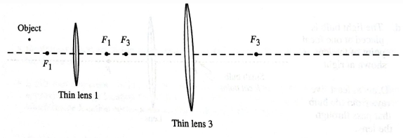
Repeat parts a andb for the case in which lens 2 is replaced with a different lens (lens 3), as shown below.

Is the image produced by the pair of lenses real or virtual? Explain your reasoning.
Expert Solution & Answer
Want to see the full answer?
Check out a sample textbook solution
Students have asked these similar questions
!
Required information
The radius of the Moon is 1.737 Mm and the distance between Earth and the Moon is 384.5 Mm.
The intensity of the moonlight incident on her eye is 0.0220 W/m². What is the intensity incident on her retina if the
diameter of her pupil is 6.54 mm and the diameter of her eye is 1.94 cm?
W/m²
Required information
An object is placed 20.0 cm from a converging lens with focal length 15.0 cm (see the figure, not drawn to scale). A
concave mirror with focal length 10.0 cm is located 76.5 cm to the right of the lens. Light goes through the lens, reflects
from the mirror, and passes through the lens again, forming a final image.
Converging
lens
Object
Concave
mirror
15.0 cm
-20.0 cm-
10.0 cm
d cm
d = 76.5.
What is the location of the final image?
cm to the left of the lens
!
Required information
A man requires reading glasses with +2.15-D refractive power to read a book held 40.0 cm away with a relaxed eye.
Assume the glasses are 1.90 cm from his eyes.
His uncorrected near point is 1.00 m. If one of the lenses is the one for distance vision, what should the refractive power of the other
lens (for close-up vision) in his bifocals be to give him clear vision from 25.0 cm to infinity?
2.98 D
Chapter 24 Solutions
Tutorials in Introductory Physics
Ch. 24.1 - On the diagram, sketch what you would see on the...Ch. 24.1 - The small bulb is replaced by three longfilament...Ch. 24.1 - The three longfilament bulbs are replaced by a...Ch. 24.1 - Predict the size and shape of the shadow that will...Ch. 24.1 - Is it possible to place the bulb in another...Ch. 24.1 - Prob. 2cTHCh. 24.1 - Prob. 2dTHCh. 24.1 - Prob. 3aTHCh. 24.1 - A student is looking at the building shown at...Ch. 24.1 - Prob. 4aTH
Ch. 24.1 - Suppose that this student were walking through the...Ch. 24.2 - The top view diagrams at right were drawn by a...Ch. 24.2 - Draw a ray diagram to determine the location of...Ch. 24.2 - Describe how you could use a ray diagram to...Ch. 24.2 - A pencil is placed in front of a plane mirror as...Ch. 24.2 - Prob. 3bTHCh. 24.3 - Prob. 1aTHCh. 24.3 - A pin is placed in front of a semicylindrical...Ch. 24.3 - Prob. 1cTHCh. 24.3 - Prob. 2aTHCh. 24.3 - A very small, very bright bulb is placed for from...Ch. 24.4 - The following are top view diagrams of solid...Ch. 24.4 - The following are top view diagrams of solid...Ch. 24.4 - The following are top view diagrams of solid...Ch. 24.4 - The following are top view diagrams of solid...Ch. 24.4 - Prob. 2THCh. 24.4 - Prob. 3aTHCh. 24.4 - Prob. 3bTHCh. 24.4 - Is the image(s) of the nail real or virtual?...Ch. 24.5 - Suppose that the bulb is placed as shown. Using...Ch. 24.5 - Prob. 1bTHCh. 24.5 - Prob. 1cTHCh. 24.5 - Prob. 1dTHCh. 24.5 - Prob. 2aTHCh. 24.5 - Treat the image produced by lens 1 as an object...Ch. 24.5 - Repeat parts a andb for the case in which lens 2...Ch. 24.6 - Reproduced below is a side view diagram of the...Ch. 24.6 - In section III of the tutorial Magnification, you...Ch. 24.6 - Two thin convex lenses and an object are arranged...Ch. 24.6 - Prob. 3bTHCh. 24.6 - Two thin convex lenses and an object are arranged...Ch. 24.6 - Prob. 3dTHCh. 24.6 - Two thin convex lenses and an object are arranged...
Additional Science Textbook Solutions
Find more solutions based on key concepts
2. Whether an allele is dominant or recessive depends on
a. how common the allele is, relative to other alleles...
Campbell Biology: Concepts & Connections (9th Edition)
Dr. Ara B. Dopsis and Dr. C. Ellie Gans are performing genetic crosses on daisy plants. They self-fertilize a b...
Genetic Analysis: An Integrated Approach (3rd Edition)
Use the key to classify each of the following described tissue types into one of the four major tissue categori...
Anatomy & Physiology (6th Edition)
Q1. Which wavelength of light has the highest frequency?
a) 10 nm
b) 10 mm
c) 1 nm
d) 1 mm
Chemistry: A Molecular Approach (4th Edition)
Why are BSL-4 suits pressurized? Why not just wear tough regular suits?
Microbiology with Diseases by Body System (5th Edition)
Explain all answers clearly, with complete sentences and proper essay structure if needed. An asterisk (*) desi...
Cosmic Perspective Fundamentals
Knowledge Booster
Learn more about
Need a deep-dive on the concept behind this application? Look no further. Learn more about this topic, physics and related others by exploring similar questions and additional content below.Similar questions
- ! Required information Assume that the magnifier is held close to the eye. Use the standard near point of 25.0 cm to find the angular magnification. An insect that is 4.10 mm long is placed 10.3 cm from a simple magnifier with a focal length of 13.0 cm. What is the angular magnification?arrow_forward2arrow_forward3arrow_forward
- Imagine you are out for a stroll on a sunny day when you encounter a lake. Unpolarized light from the sun is reflected off the lake into your eyes. However, you notice when you put on your vertically polarized sunglasses, the light reflected off the lake no longer reaches your eyes. What is the angle between the unpolarized light and the surface of the water, in degrees, measured from the horizontal? You may assume the index of refraction of air is nair=1 and the index of refraction of water is nwater=1.33 . Round your answer to three significant figures. Just enter the number, nothing else.arrow_forwardDeduce what overvoltage is like in reversible electrodes.arrow_forwardpls help on thesearrow_forward
- pls help on thesearrow_forward20. Two small conducting spheres are placed on top of insulating pads. The 3.7 × 10⁻¹⁰ C sphere is fixed whie the 3.0 × 10⁷ C sphere, initially at rest, is free to move. The mass of each sphere is 0.09 kg. If the spheres are initially 0.10 m apart, how fast will the sphere be moving when they are 1.5 m apart?arrow_forwardpls help on allarrow_forward
arrow_back_ios
SEE MORE QUESTIONS
arrow_forward_ios
Recommended textbooks for you
 University Physics Volume 3PhysicsISBN:9781938168185Author:William Moebs, Jeff SannyPublisher:OpenStax
 Glencoe Physics: Principles and Problems, Student...PhysicsISBN:9780078807213Author:Paul W. ZitzewitzPublisher:Glencoe/McGraw-Hill
 Physics for Scientists and Engineers: Foundations...PhysicsISBN:9781133939146Author:Katz, Debora M.Publisher:Cengage Learning
 Principles of Physics: A Calculus-Based TextPhysicsISBN:9781133104261Author:Raymond A. Serway, John W. JewettPublisher:Cengage Learning
 An Introduction to Physical SciencePhysicsISBN:9781305079137Author:James Shipman, Jerry D. Wilson, Charles A. Higgins, Omar TorresPublisher:Cengage Learning
 Physics for Scientists and EngineersPhysicsISBN:9781337553278Author:Raymond A. Serway, John W. JewettPublisher:Cengage Learning

University Physics Volume 3
Physics
ISBN:9781938168185
Author:William Moebs, Jeff Sanny
Publisher:OpenStax

Glencoe Physics: Principles and Problems, Student...
Physics
ISBN:9780078807213
Author:Paul W. Zitzewitz
Publisher:Glencoe/McGraw-Hill

Physics for Scientists and Engineers: Foundations...
Physics
ISBN:9781133939146
Author:Katz, Debora M.
Publisher:Cengage Learning

Principles of Physics: A Calculus-Based Text
Physics
ISBN:9781133104261
Author:Raymond A. Serway, John W. Jewett
Publisher:Cengage Learning

An Introduction to Physical Science
Physics
ISBN:9781305079137
Author:James Shipman, Jerry D. Wilson, Charles A. Higgins, Omar Torres
Publisher:Cengage Learning

Physics for Scientists and Engineers
Physics
ISBN:9781337553278
Author:Raymond A. Serway, John W. Jewett
Publisher:Cengage Learning
Domestic Electric Circuits; Author: PrepOnGo Class 10 & 12;https://www.youtube.com/watch?v=2ZvWaloQ3nk;License: Standard YouTube License, CC-BY