Concept explainers
Videos
To identify: The device obtained by connecting a resistor in shunt with a galvanometer.
Answer to Problem 57A
The device obtained by connecting a resistor in shunt with galvanometer is an ammeter.
Explanation of Solution
Given:
A galvanometer with a resistor connected in parallel to it.
Consider the circuit shown in Figure 1. The circuit consists of a galvanometer which can be used to measure small currents. The resistor connected in parallel with the galvanometer is called as “shunt resistor”. This resistor has a value less than the resistance of the galvanometer. It is converted to an ammeter using circuit.
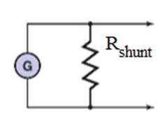
Figure 1
In this circuit, the effective resistance of the coil of the galvanometer is reduced from its original value of around 1000 Ω to a lower value decided by the shunt resistance across the meter. Due to the presence of shunt resistance, more current flows through the shunt resistor than the galvanometer. This produces a corresponding deflection in the meter scale and hence measures the current.
Thus, by connecting a resistor in shunt with the galvanometer, it can be made to work as an ammeter.
Chapter 24 Solutions
Glencoe Physics: Principles and Problems, Student Edition
Additional Science Textbook Solutions
Campbell Biology (11th Edition)
Concepts of Genetics (12th Edition)
Genetic Analysis: An Integrated Approach (3rd Edition)
Applications and Investigations in Earth Science (9th Edition)
College Physics: A Strategic Approach (3rd Edition)
Human Anatomy & Physiology (2nd Edition)


- Hi! I need help with these calculations for part i and part k for a physics Diffraction Lab. We used a slit width 0.4 mm to measure our pattern.arrow_forwardExamine the data and % error values in Data Table 3 where the angular displacement of the simple pendulum decreased but the mass of the pendulum bob and the length of the pendulum remained constant. Describe whether or not your data shows that the period of the pendulum depends on the angular displacement of the pendulum bob, to within a reasonable percent error.arrow_forwardIn addition to the anyalysis of the graph, show mathematically that the slope of that line is 2π/√g . Using the slope of your line calculate the value of g and compare it to 9.8.arrow_forward
- An object is placed 24.1 cm to the left of a diverging lens (f = -6.51 cm). A concave mirror (f= 14.8 cm) is placed 30.2 cm to the right of the lens to form an image of the first image formed by the lens. Find the final image distance, measured relative to the mirror. (b) Is the final image real or virtual? (c) Is the final image upright or inverted with respect to the original object?arrow_forwardConcept Simulation 26.4 provides the option of exploring the ray diagram that applies to this problem. The distance between an object and its image formed by a diverging lens is 5.90 cm. The focal length of the lens is -2.60 cm. Find (a) the image distance and (b) the object distance.arrow_forwardPls help ASAParrow_forward
 College PhysicsPhysicsISBN:9781305952300Author:Raymond A. Serway, Chris VuillePublisher:Cengage Learning
 University Physics (14th Edition)PhysicsISBN:9780133969290Author:Hugh D. Young, Roger A. FreedmanPublisher:PEARSON
 Introduction To Quantum MechanicsPhysicsISBN:9781107189638Author:Griffiths, David J., Schroeter, Darrell F.Publisher:Cambridge University Press
 Physics for Scientists and EngineersPhysicsISBN:9781337553278Author:Raymond A. Serway, John W. JewettPublisher:Cengage Learning
 Lecture- Tutorials for Introductory AstronomyPhysicsISBN:9780321820464Author:Edward E. Prather, Tim P. Slater, Jeff P. Adams, Gina BrissendenPublisher:Addison-Wesley
 College Physics: A Strategic Approach (4th Editio...PhysicsISBN:9780134609034Author:Randall D. Knight (Professor Emeritus), Brian Jones, Stuart FieldPublisher:PEARSON