Concept explainers
BIO Footwear Safety
The American National Standards Institute (ANSI) specifies safety standards for a number of potential workplace hazards. For example, ANSI requires that footwear provide protection against the effects of compression from a static weight, impact from a dropped object, puncture from a sharp tool, and cuts from saws. In addition, to protect against the potentially lethal effects of an electrical shock, ANSI provides standards for the electrical resistance that a person and footwear must offer to the flow of
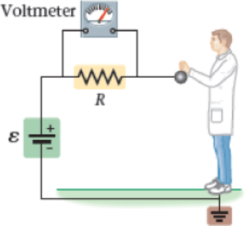
Specifically, regulation ANSI Z41-1999 states that the resistance of a person and his or her footwear must be tested with the circuit shown in Figure 21-63. In this circuit, the voltage supplied by the battery is ɛ = 50.0 V and the resistance in the circuit is R = 1.00 MΩ. Initially the circuit is open and no current flows. When a person touches the metal sphere attached to the battery, however, the circuit is closed and a small current flows through the person, the shoes, and back to the battery. The amount of current flowing through the person can be determined by using a voltmeter to measure the voltage drop V across the resistor R. To be safe, the current should not exceed 150 µF.

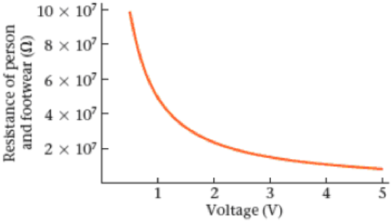
Notice that the experimental setup in Figure 21-63 is a dc circuit with two resistors in series—the resistance R and the resistance of the person and footwear, Rpf. It follows that the current in the circuit is I = ɛ/(R + Rpf). We also know that the current is I = V/R, where V is the reading of the voltmeter. These relationships can be combined to relate the voltage V to the resistance Rpf with the result shown in Figure 21-64. According to ANSI regulations, Type II footwear must give a resistance Rpf in the range of 0.1 × 10⁷ Ω to 100 × 107 Ω.
Figure 21-63 Problems 103, 104, 105, and 106

105. • The resistance of a given person and footwear is 4.00 × 10⁷ Ω. What is the reading on the voltmeter when this person is tested?
- A. 0.976 V
- B. 1.22 V
- C. 1.25 V
- D. 50.0 V
Want to see the full answer?
Check out a sample textbook solution
Chapter 21 Solutions
EBK PHYSICS
Additional Science Textbook Solutions
Biology: Life on Earth (11th Edition)
Genetic Analysis: An Integrated Approach (3rd Edition)
Campbell Biology in Focus (2nd Edition)
Organic Chemistry (8th Edition)
Anatomy & Physiology (6th Edition)
Microbiology: An Introduction
- No chatgpt pls will upvotearrow_forwardExperimental Research Report Template Title: Paper Airplane Flight. Materials: Paper, ruler, tape Procedure: Fold paper into different airplane designs, such as dart, glider, or classic. Measure and record the distances each design flies when thrown with the same force. Discuss aerodynamics and the factors that affect flight distance. Introduction: (What do you expect to learn? What is the purpose of this lab? List any questions this experiment will answer.) Hypothesis: (Predict the outcome(s) of the experiment, must be in an “if…then format.) Materials: (What equipment and materials did you need for this experiment assignment? Describe how any equipment was connected. Also mention any special hardware or connections. List the name and amount of each item used.) Procedures: (What steps did you take to accomplish this lab assignment? Include Safety Precautions.) Data Collection: (Record the data that is required at each step of the…arrow_forwardTitle: Studying the Relationship Between Drop Height and Bouncing Height of a Ball: You can drop balls of different materials (e.g., rubber, plastic, ping pong) from various heights onto a flat surface and measure the height of their bounce using a ruler. Introduction: (What do you expect to learn? What is the purpose of this lab? List any questions this experiment will answer.) Hypothesis: (Predict the outcome(s) of the experiment, must be in an “if…then format.) Materials: (What equipment and materials did you need for this experiment assignment? Describe how any equipment was connected. Also mention any special hardware or connections. List the name and amount of each item used.) Procedures: (What steps did you take to accomplish this lab assignment? Include Safety Precautions.) Data Collection: (Record the data that is required at each step of the lab: tables, charts, graphs, sketches, etc.) Data Analysis: (Explain you…arrow_forward
- A traveler at an airport takes an escalator up one floor as in the figure below. The moving staircase would itself carry him upward with vertical velocity component v between entry and exit points separated by height h. However, while the escalator is moving, the hurried traveler climbs the steps of the escalator at a rate of n steps/s. Assume that the height of each step is hs. (a) Determine the amount of chemical energy converted into mechanical energy by the traveler's leg muscles during his escalator ride given that his mass is m. (Use any variable or symbol stated above along with the following as necessary: g.) energy = (b) Determine the work the escalator motor does on this person. (Use any variable or symbol stated above along with the following as necessary: g.) work =arrow_forwardWhich of the following is part of the interior of the Sun? photosphere the corona sunspots radiation zonearrow_forwardMost craters on the surface of the Moon are believed to be caused by which of the following? faults asteroids volcanoes meteoroidsarrow_forward
- An object is subjected to a friction force with magnitude 5.49 N, which acts against the object's velocity. What is the work (in J) needed to move the object at constant speed for the following routes? y (m) C B (5.00, 5.00) A x (m) © (a) the purple path O to A followed by a return purple path to O ] (b) the purple path O to C followed by a return blue path to O ] (c) the blue path O to C followed by a return blue path to O ] (d) Each of your three answers should be nonzero. What is the significance of this observation? ○ The force of friction is a conservative force. ○ The force of friction is a nonconservative force.arrow_forwardA block of mass m = 2.50 kg is pushed d = 2.30 m along a frictionless horizontal table by a constant applied force of magnitude F = 10.0 N directed at an angle 25.0° below the horizontal as shown in the figure below. m (a) Determine the work done by the applied force. ] (b) Determine the work done by the normal force exerted by the table. ] (c) Determine the work done by the force of gravity. ] (d) Determine the work done by the net force on the block. ]arrow_forwardA man pushing a crate of mass m = 92.0 kg at a speed of v = 0.845 m/s encounters a rough horizontal surface of length = 0.65 m as in the figure below. If the coefficient of kinetic friction between the crate and rough surface is 0.357 and he exerts a constant horizontal force of 294 N on the crate. e (a) Find the magnitude and direction of the net force on the crate while it is on the rough surface. magnitude direction ---Select--- N (b) Find the net work done on the crate while it is on the rough surface. ] (c) Find the speed of the crate when it reaches the end of the rough surface. m/sarrow_forward
- Two blocks, A and B (with mass 45 kg and 120 kg, respectively), are connected by a string, as shown in the figure below. The pulley is frictionless and of negligible mass. The coefficient of kinetic friction between block A and the incline is μk = 0.26. Determine the change in the kinetic energy of block A as it moves from to, a distance of 15 m up the incline (and block B drops downward a distance of 15 m) if the system starts from rest. × J 37° Barrow_forwardYou are working for the Highway Department. In mountainous regions, highways sometimes include a runaway truck ramp, and you are asked to help with the design of such a ramp. A runaway truck ramp is often a lane of gravel adjacent to a long downhill section of roadway where trucks with failing brakes may need assistance to stop. Working with your supervisor, you develop a worst-case scenario: a truck with a mass of 6.00 × 10⁴ kg enters a runaway truck lane traveling at 34.1 m/s. Assume that the maximum constant value for safe acceleration of the truck is -5.00 m/s². Any higher magnitude of acceleration increases the likelihood that semi-trailer rigs could jackknife. Your supervisor asks you to advise her on the required length (in m) of a runaway truck lane on a flat section of ground next to the roadway. marrow_forwardA large cruise ship of mass 6.20 × 10⁷ kg has a speed of 10.2 m/s at some instant. (a) What is the ship's kinetic energy at this time? ] (b) How much work is required to stop it? (Give the work done on the ship. Include the sign of the value in your answer.) ] (c) What is the magnitude of the constant force required to stop it as it undergoes a displacement of 3.10 km? Narrow_forward
 Physics for Scientists and Engineers: Foundations...PhysicsISBN:9781133939146Author:Katz, Debora M.Publisher:Cengage Learning
 Physics for Scientists and Engineers with Modern ...PhysicsISBN:9781337553292Author:Raymond A. Serway, John W. JewettPublisher:Cengage Learning
 Physics for Scientists and EngineersPhysicsISBN:9781337553278Author:Raymond A. Serway, John W. JewettPublisher:Cengage Learning
 College PhysicsPhysicsISBN:9781938168000Author:Paul Peter Urone, Roger HinrichsPublisher:OpenStax College
 Physics for Scientists and Engineers, Technology ...PhysicsISBN:9781305116399Author:Raymond A. Serway, John W. JewettPublisher:Cengage Learning


