
Fox and McDonald's Introduction to Fluid Mechanics
9th Edition
ISBN: 9781118912652
Author: Philip J. Pritchard, John W. Mitchell
Publisher: WILEY
expand_more
expand_more
format_list_bulleted
Videos
Textbook Question
Chapter 2, Problem 55P
Calculate the approximate power lost in friction in this ship propeller shaft bearing.
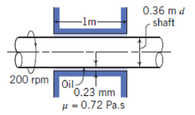
P2.55
Expert Solution & Answer
Want to see the full answer?
Check out a sample textbook solution
Students have asked these similar questions
%94 KB/S
Find : 1. dynamic load on each bearing due to the out-of-balance couple; and 2. kinetic energy of
the complete assembly.
[Ans. 6.12 kg: 8.7 N-m]
L
2.
3.
4.
5.
1.
2.
5.
DO YOU KNOW?
Why is balancing of rotating parts necessary for high speed engines?
Explain clearly the terms "static balancing' and 'dynamic balancing'. State the necessary conditions
to achieve them.
Discuss how a single revolving mass is balanced by two masses revolving in different planes.
Chapter 21: Balancing of Rotating Masses .857
Explain the method of balancing of different masses revolving in the same plane.
How the different masses rotating in different planes are balanced?
OBJECTIVE TYPE QUESTIONS
The balancing of rotating and reciprocating parts of an engine is necessary when it runs at
(a) slow speed
(b) medium speed (c) high speed
A disturbing mass, attached to a rotating shaft may be balanced by a single mass m, attached in
the same plane of rotation as that of my such that
(a)
(b) F
For static…
Provide a real-world usage example of the following:
Straightness
Circularity
Parallelism
What specific tools, jigs, and other devices are used to control the examples you provided?
856 Theory of Machines
5.
A shaft carries five masses A, B, C, D and E which revolve at the same radius in planes which are
equidistant from one another. The magnitude of the masses in planes A, C and D are 50 kg, 40 kg
and 80 kg respectively. The angle between A and C is 90° and that between C and D is 135°
Determine the magnitude of the masses in planes B and E and their positions to put the shaft in
complete rotating balance.
[Ans. 12 kg, 15 kg; 130° and 24° from mass A in anticlockwise direction]
Chapter 2 Solutions
Fox and McDonald's Introduction to Fluid Mechanics
Ch. 2 - For the velocity fields given below, determine:...Ch. 2 - For the velocity fields given below, determine:...Ch. 2 - A viscous liquid is sheared between two parallel...Ch. 2 - For the velocity field V=Ax2yi+Bxy2j, where A = 2...Ch. 2 - A fluid flow has the following velocity...Ch. 2 - When an incompressible, nonviscous fluid flows...Ch. 2 - For the free vortex flow the velocities are t =...Ch. 2 - For the forced vortex flow the velocities are t =...Ch. 2 - A velocity field is specified as V=axyi+by2j,...Ch. 2 - A velocity field is given by V=ax3i+bxy3j, where a...
Ch. 2 - The velocity for a steady, incompressible flow in...Ch. 2 - The flow field for an atmospheric flow is given by...Ch. 2 - For the velocity field V=AxiAyj,, where A = 2s 1....Ch. 2 - A velocity field in polar coordinates is given...Ch. 2 - The flow of air near the Earths surface is...Ch. 2 - A velocity field is given by V=aytibxj, where a =...Ch. 2 - Air flows downward toward an infinitely wide...Ch. 2 - Consider the flow described by the velocity field...Ch. 2 - Consider the velocity field V = axi + by(1 + ct)...Ch. 2 - Consider the flow field given in Eulerian...Ch. 2 - A velocity field is given by V=axti+byj, where A =...Ch. 2 - Consider the garden hose of Fig. 2.5. Suppose the...Ch. 2 - Consider the velocity field of Problem 2.18. Plot...Ch. 2 - Streaklines are traced out by neutrally buoyant...Ch. 2 - Consider the flow field V=axti+bj, where a = 1/s2...Ch. 2 - A flow is described by velocity field V=ay2i+bj,...Ch. 2 - Tiny hydrogen bubbles are being used as tracers to...Ch. 2 - A flow is described by velocity field V=ai+bxj,...Ch. 2 - A flow is described by velocity field V=ayi+btj,...Ch. 2 - A flow is described by velocity field V=ati+bj,...Ch. 2 - The variation with temperature of the viscosity of...Ch. 2 - The variation with temperature of the viscosity of...Ch. 2 - Some experimental data for the viscosity of helium...Ch. 2 - The velocity distribution for laminar flow between...Ch. 2 - What is the ratio between the viscosities of air...Ch. 2 - Calculate velocity gradients and shear stress for...Ch. 2 - A very large thin plate is centered in a gap of...Ch. 2 - A female freestyle ice skater, weighing 100 lbf,...Ch. 2 - A block of mass 10 kg and measuring 250 mm on each...Ch. 2 - A 73-mm-diameter aluminum (SG = 2.64) piston of...Ch. 2 - A vertical gap 25 mm wide of infinite extent...Ch. 2 - A cylinder 8 in. in diameter and 3 ft long is...Ch. 2 - Crude oil at 20C fills the space between two...Ch. 2 - The piston in Problem 2.40 is traveling at...Ch. 2 - A block of mass M slides on a thin film of oil....Ch. 2 - A block 0.1 m square, with 5 kg mass, slides down...Ch. 2 - A torque of 4 N m is required to rotate the...Ch. 2 - A circular disk of diameter d is slowly rotated in...Ch. 2 - The fluid drive shown transmits a torque T for...Ch. 2 - A block that is a mm square slides across a flat...Ch. 2 - In a food-processing plant, honey is pumped...Ch. 2 - SAE 10W-30 oil at 100C is pumped through a tube L...Ch. 2 - The lubricant has a kinematic viscosity of 2:8105...Ch. 2 - Calculate the approximate viscosity of the oil....Ch. 2 - Calculate the approximate power lost in friction...Ch. 2 - Fluids of viscosities 1 = 0.1 Ns/m2 and 2 = 0.15...Ch. 2 - A concentric cylinder viscometer may be formed by...Ch. 2 - A concentric cylinder viscometer is driven by a...Ch. 2 - A shaft with outside diameter of 18 mm turns at 20...Ch. 2 - A shock-free coupling for a low-power mechanical...Ch. 2 - A proposal has been made to use a pair of parallel...Ch. 2 - The cone and plate viscometer shown is an...Ch. 2 - A viscometer is used to measure the viscosity of a...Ch. 2 - A concentric-cylinder viscometer is shown. Viscous...Ch. 2 - Design a concentric-cylinder viscometer to measure...Ch. 2 - A cross section of a rotating bearing is shown....Ch. 2 - Small gas bubbles form in soda when a bottle or...Ch. 2 - You intend to gently place several steel needles...Ch. 2 - According to Folsom [6], the capillary rise h...Ch. 2 - Calculate and plot the maximum capillary rise of...Ch. 2 - Calculate the maximum capillary rise of water...Ch. 2 - Calculate the maximum capillary depression of...Ch. 2 - Water usually is assumed to be incompressible when...Ch. 2 - The viscous boundary layer velocity profile shown...Ch. 2 - In a food industry process, carbon tetrachloride...Ch. 2 - What is the Reynolds number of water at 20C...Ch. 2 - A supersonic aircraft travels at 2700 km/hr at an...Ch. 2 - SAE 30 oil at 100C flows through a 12-mm-diameter...Ch. 2 - A seaplane is flying at 100 mph through air at...Ch. 2 - An airliner is cruising at an altitude of 5.5 km...
Additional Engineering Textbook Solutions
Find more solutions based on key concepts
?.1 Define the different reference meridians that can be used for the direction ofa line.
Elementary Surveying: An Introduction To Geomatics (15th Edition)
A file that contains a Flash animation uses the __________ file extension. a. .class b. .swf c. .mp3 d. .flash
Web Development and Design Foundations with HTML5 (8th Edition)
What is a module?
Starting Out with Programming Logic and Design (5th Edition) (What's New in Computer Science)
What is the disadvantage of having too many features in a language?
Concepts Of Programming Languages
For the circuit shown, use the node-voltage method to find v1, v2, and i1.
How much power is delivered to the c...
Electric Circuits. (11th Edition)
Explain the term cursor.
Database Concepts (8th Edition)
Knowledge Booster


Learn more about
Need a deep-dive on the concept behind this application? Look no further. Learn more about this topic, mechanical-engineering and related others by exploring similar questions and additional content below.Similar questions
- 2. 3. 4. clockwise from Four masses A, B, C and D revolve at equal radii and are equally spaced along a shaft. The mass B is 7 kg and the radii of C and D make angles of 90° and 240° respectively with the radius of B. Find the magnitude of the masses A, C and D and the angular position of A so that the system may be completely balanced. [Ans. 5 kg: 6 kg; 4.67 kg; 205° from mass B in anticlockwise direction] A rotating shaft carries four masses A, B, C and D which are radially attached to it. The mass centres are 30 mm, 38 mm, 40 mm and 35 mm respectively from the axis of rotation. The masses A, C and D are 7.5 kg. 5 kg and 4 kg respectively. The axial distances between the planes of rotation of A and B is 400 mm and between B and C is 500 mm. The masses A and C are at right angles to each other. Find for a complete balance, 1. the angles between the masses B and D from mass A, 2. the axial distance between the planes of rotation of C and D. 3. the magnitude of mass B. [Ans. 162.5%,…arrow_forward1. Four masses A, B, C and D are attached to a shaft and revolve in the same plane. The masses are 12 kg. 10 kg. 18 kg and 15 kg respectively and their radii of rotations are 40 mm, 50 mm, 60 mm and 30 mm. The angular position of the masses B, C and D are 60°, 135° and 270 from the mass A. Find the magnitude and position of the balancing mass at a radius of 100 mm. [Ans. 7.56 kg: 87 clockwise from A]arrow_forward3. The structure in Figure 3 is loaded by a horizontal force P = 2.4 kN at C. The roller at E is frictionless. Find the axial force N, the shear force V and the bending moment M at a section just above the pin B in the member ABC and illustrate their directions on a sketch of the segment AB. B P D A 65° 65° E all dimensions in meters Figure 3arrow_forward
- 4. The distributed load in Figure 4 varies linearly from 3wo per unit length at A to wo per unit length at B and the beam is built in at A. Find expressions for the shear force V and the bending moment M as functions of x. 3W0 Wo A L Figure 4 2 Barrow_forward1. The beam AB in Figure 1 is subjected to a uniformly distributed load wo = 100 N/m. Find the axial force N, the shear force V and the bending moment M at the point D which is midway between A and B and illustrate their directions on a sketch of the segment DB. wo per unit length A D' B all dimensions in metersarrow_forward5. Find the shear force V and the bending moment M for the beam of Figure 5 as functions of the distance x from A. Hence find the location and magnitude of the maximum bending moment. w(x) = wox L x L Figure 5 Barrow_forward
- Dry atmospheric air enters an adiabatic compressor at a 20°C, 1 atm and a mass flow rate of 0.3kg/s. The air is compressed to 1 MPa. The exhaust temperature of the air is 70 degrees hottercompared to the exhaust of an isentropic compression.Determine,a. The exhaust temperature of the air (°C)b. The volumetric flow rate (L/s) at the inlet and exhaust of the compressorc. The power required to accomplish the compression (kW)d. The isentropic efficiency of the compressore. An accounting of the exergy entering the compressor (complete Table P3.9) assuming that thedead state is the same as State 1 (dry atmospheric air)f. The exergetic efficiency of the compressorarrow_forwardA heat pump is operating between a low temperature reservoir of 270 K and a high temperaturereservoir of 340 K. The heat pump receives heat at 255 K from the low temperature reservoir andrejects heat at 355 K to the high temperature reservoir. The heating coefficient of performance ofthe heat pump is 3.2. The heat transfer rate from the low temperature reservoir is 30 kW. The deadstate temperature is 270 K. Determine,a. Power input to the heat pump (kW)b. Heat transfer rate to the high-temperature reservoir (kW)c. Exergy destruction rate associated with the low temperature heat transfer (kW)d. Exergy destruction rate of the heat pump (kW)e. Exergy destruction rate associated with the high temperature heat transfer (kW)f. Exergetic efficiency of the heat pump itselfarrow_forwardRefrigerant 134a (Table B6, p514 of textbook) enters a tube in the evaporator of a refrigerationsystem at 132.73 kPa and a quality of 0.15 at a velocity of 0.5 m/s. The R134a exits the tube as asaturated vapor at −21°C. The tube has an inside diameter of 3.88 cm. Determine the following,a. The pressure drop of the R134a as it flows through the tube (kPa)b. The volumetric flow rate at the inlet of the tube (L/s)c. The mass flow rate of the refrigerant through the tube (g/s)d. The volumetric flow rate at the exit of the tube (L/s)e. The velocity of the refrigerant at the exit of the tube (m/s)f. The heat transfer rate to the refrigerant (kW) as it flows through the tubearrow_forward
- Water enters the rigid, covered tank shown in Figure P3.2 with a volumetric flow rate of 0.32L/s. The water line has an inside diameter of 6.3 cm. The air vent on the tank has an inside diameterof 4.5 cm. The water is at a temperature of 30°C and the air in the tank is at atmospheric pressure(1 atm) and 30°C. Determine the air velocity leaving the vent at the instant shown in the figurearrow_forwardUsing method of sections, determine the force in member BC, HC, and HG. State if these members are in tension or compression. 2 kN A 5 kN 4 kN 4 kN 3 kN H B C D E 3 m F 2 m -5 m 5 m- G 5 m 5 m-arrow_forwardDetermine the normal stresses σn and σt and the shear stress τnt at this point if they act on the rotated stress element shownarrow_forward
arrow_back_ios
SEE MORE QUESTIONS
arrow_forward_ios
Recommended textbooks for you
 Elements Of ElectromagneticsMechanical EngineeringISBN:9780190698614Author:Sadiku, Matthew N. O.Publisher:Oxford University Press
 Mechanics of Materials (10th Edition)Mechanical EngineeringISBN:9780134319650Author:Russell C. HibbelerPublisher:PEARSON
 Thermodynamics: An Engineering ApproachMechanical EngineeringISBN:9781259822674Author:Yunus A. Cengel Dr., Michael A. BolesPublisher:McGraw-Hill Education
 Control Systems EngineeringMechanical EngineeringISBN:9781118170519Author:Norman S. NisePublisher:WILEY
 Mechanics of Materials (MindTap Course List)Mechanical EngineeringISBN:9781337093347Author:Barry J. Goodno, James M. GerePublisher:Cengage Learning
 Engineering Mechanics: StaticsMechanical EngineeringISBN:9781118807330Author:James L. Meriam, L. G. Kraige, J. N. BoltonPublisher:WILEY
Elements Of Electromagnetics
Mechanical Engineering
ISBN:9780190698614
Author:Sadiku, Matthew N. O.
Publisher:Oxford University Press
Mechanics of Materials (10th Edition)
Mechanical Engineering
ISBN:9780134319650
Author:Russell C. Hibbeler
Publisher:PEARSON
Thermodynamics: An Engineering Approach
Mechanical Engineering
ISBN:9781259822674
Author:Yunus A. Cengel Dr., Michael A. Boles
Publisher:McGraw-Hill Education
Control Systems Engineering
Mechanical Engineering
ISBN:9781118170519
Author:Norman S. Nise
Publisher:WILEY
Mechanics of Materials (MindTap Course List)
Mechanical Engineering
ISBN:9781337093347
Author:Barry J. Goodno, James M. Gere
Publisher:Cengage Learning
Engineering Mechanics: Statics
Mechanical Engineering
ISBN:9781118807330
Author:James L. Meriam, L. G. Kraige, J. N. Bolton
Publisher:WILEY
Physics 33 - Fluid Statics (1 of 10) Pressure in a Fluid; Author: Michel van Biezen;https://www.youtube.com/watch?v=mzjlAla3H1Q;License: Standard YouTube License, CC-BY