INTRO.TO COMPUTING SYSTEMS >INTL.ED.<
3rd Edition
ISBN: 9781260565911
Author: PATT
Publisher: MCG
expand_more
expand_more
format_list_bulleted
Question
Chapter 2, Problem 34E
a.
Program Plan Intro
NOT operation:
- NOT function needs one input and produces one output.
- It is also known as unary logical function.
- Another name of NOT operation is complementary operation.
- Output is produced by complementing the input.
- The following diagram depicts the NOT operation,

- The NOT operation produces the output “1”, when the source input is “0”.
- The NOT operation produces the output “0”, when the source input is “1”.
- The truth table for the NOT operation is as follows,
| X | |
| 0 | 1 |
| 1 | 0 |
- In the above table, “X” is the input, and “Z” is the output.
- When “X=0”, the output “Z” is the complement of “0”, which means “1” and When “X=1”,the output “Z” is the complement of “1”, which means “0”.
OR operation:
- OR function needs two inputs and produces one output.
- It is also known as binary logical function.
- If one of the inputs or both the inputs are “1”, then one-bit OR operation produces the output as “1”.
- If both the inputs are “0”, then OR operation produces the output “0”.
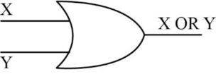
- The following diagram depicts the one-bit OR operation,

- The truth table for OR operation is as follows,
| X | Y | Z=X OR Y |
| 0 | 0 | 0 |
| 0 | 1 | 1 |
| 1 | 0 | 1 |
| 1 | 1 | 1 |
- In the above table, “X” and “Y” are the inputs, and “Z” is the output.
- In the above table, when “X=0”, and “Y=0”, the output “Z” is “0”, because both the inputs “X” and “Y” contains the value “0”.
- When “X=0”, and “Y=1”, the output “Z” is “1”, because one of the input “Y” contains the value “1”.
- When “X=1”, and “Y=0”, the output “Z” is “1”, because one of the input “X” contains the value “1”.
- When “X=1”, and “Y=1”, the output “Z” is “1”, because both the inputs “X” and “Y” contains the value “1”.
AND function:
- AND function needs two inputs and produces one output.
- It is also known as binary logical function.
- If one or both the inputs are “0”, then one-bit AND operation produces the output “0”.
- If both inputs are “1”, then AND operation produces the output as “1”.
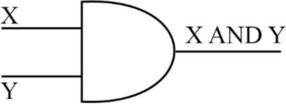
- The following diagram depicts the AND operation,

- The truth table for AND operation is as follows,
| X | Y | X AND Y |
| 0 | 0 | 0 |
| 0 | 1 | 0 |
| 1 | 0 | 0 |
| 1 | 1 | 1 |
- In the above table, “X” and “Y” are inputs, and “Z” is output.
- When “X=0”, and “Y=0”, the output is “0”, because both the inputs “X” and “Y” contains the value “0”.
- When “X=0”, and “Y=1”, the output is “0”, because one of the input “X” contains the value “0”.
- When “X=1”, and “Y=0”, the output is “0”, because one of the input “Y” contains the value “0”.
- When “X=1”, and “Y=1”, the output is “1”, because both the inputs “X” and “Y” contains the value “1”.
b.
Explanation of Solution
To compute “NOT (1000 AND (1100 OR 0101))”:
- To compute “(1100 OR 0101)”,
- The OR operation can be applied on each pair of bits individually and hence it is called bit-wise OR operation.
- The OR operation for the binary numbers “1100” and “0101” is as follows,
- The output bit is “1”, when one or both of the input bits are “1” and the output bit is “0”, when both the input bits are “0”.
- The result of “(1100 OR 0101)” is “1101”.
- To compute “1000 AND (1100 OR 0101))”,
- Compute the AND operation for the binary number “1000” and the result “1101”.
- The AND operation can be applied on each pair of bits individually and hence it is called bit-wise AND operation.
- The AND operation for the given binary number is as follows,
c.
Explanation of Solution
To compute “NOT(NOT(1101))”:
- First compute “NOT (1101)”,
- The NOT operation can be applied on each bits individually and hence it is called bit-wise NOT operation.
- The NOT operation for the binary number “1101” is as follows,
- The output bit is “0”, when the input bit is “1” and the output bit is “1”, when the input bit is “0”.
- The result of the above calculation is “0010”...
d.
Explanation of Solution
To compute “(0110 OR 0000) AND 1111”:
- First compute “(0110 OR 0000)”,
- The OR operation can be applied on each pair of bits individually and hence it is called bit-wise OR operation.
- The OR operation for the given binary number is as follows,
- The output bit is “1”, when one or both of the input bits are “1” and the output bit is “0”, when both the input bits are “0”.
- The result of the above calculation is “0110”.
- Compute “0110 AND 1111”,
- The AND operation can be applied on each pair of bits individually and hence it is called bit-wise AND operation...
Expert Solution & Answer
Want to see the full answer?
Check out a sample textbook solution
Students have asked these similar questions
Please answer the question correctly please. Thank you!!
Please answer the question correctly please. Thank you!!
Please answer the question correctly please. Thank you!!
Chapter 2 Solutions
INTRO.TO COMPUTING SYSTEMS >INTL.ED.<
Ch. 2 - Prob. 1ECh. 2 - Prob. 2ECh. 2 - Prob. 3ECh. 2 - Prob. 4ECh. 2 - Prob. 5ECh. 2 - Prob. 6ECh. 2 - Prob. 7ECh. 2 - Prob. 8ECh. 2 - Prob. 9ECh. 2 - Prob. 10E
Ch. 2 - Prob. 11ECh. 2 - Prob. 12ECh. 2 - Prob. 13ECh. 2 - Prob. 14ECh. 2 - Prob. 15ECh. 2 - Prob. 17ECh. 2 - Prob. 18ECh. 2 - Prob. 19ECh. 2 - Prob. 20ECh. 2 - Prob. 21ECh. 2 - Prob. 22ECh. 2 - Prob. 23ECh. 2 - Prob. 24ECh. 2 - Prob. 25ECh. 2 - Prob. 26ECh. 2 - Prob. 27ECh. 2 - When is the output of an AND operation equal to...Ch. 2 - Prob. 29ECh. 2 - Prob. 30ECh. 2 - When is the output of an OR operation equal to 1?
Ch. 2 - Prob. 32ECh. 2 - Prob. 33ECh. 2 - Prob. 34ECh. 2 - Prob. 35ECh. 2 - Prob. 36ECh. 2 - Prob. 37ECh. 2 - Prob. 38ECh. 2 - Prob. 39ECh. 2 - Prob. 40ECh. 2 - Prob. 41ECh. 2 - A computer programmer wrote a program that adds...Ch. 2 - Prob. 43ECh. 2 - Prob. 44ECh. 2 - Prob. 45ECh. 2 - Prob. 46ECh. 2 - Prob. 47ECh. 2 - Prob. 48ECh. 2 - Prob. 49ECh. 2 - Prob. 50ECh. 2 - Prob. 51ECh. 2 - Prob. 52ECh. 2 - Prob. 53ECh. 2 - Fill in the truth table for the equations given....Ch. 2 - Prob. 55ECh. 2 - Prob. 56E
Knowledge Booster
Similar questions
- Considering the TM example of binary sum ( see attached)do the step-by-step of execution for the binary numbers 1101 and 11. Feel free to use the Formal Language Editor Tool to execute it; Write it down the current state of the tape (including the head position) and indicate the current state of the TM at each step.arrow_forwardI need help on inculding additonal code where I can can do the opposite code of MatLab, where the function of t that I enter becomes the result of F(t), in other words, turning the time-domain f(t) into the frequency-domain function F(s):arrow_forwardI need help with the TM computation step-by-step execution for the binary numbers 1101 and 11. Formal Language Editor Tool can be used to execute it; Write it down the current state of the tape (including the head position) and indicate the current state of the TM at each step;arrow_forward
arrow_back_ios
SEE MORE QUESTIONS
arrow_forward_ios
Recommended textbooks for you
 Database System ConceptsComputer ScienceISBN:9780078022159Author:Abraham Silberschatz Professor, Henry F. Korth, S. SudarshanPublisher:McGraw-Hill Education
 Starting Out with Python (4th Edition)Computer ScienceISBN:9780134444321Author:Tony GaddisPublisher:PEARSON
 Digital Fundamentals (11th Edition)Computer ScienceISBN:9780132737968Author:Thomas L. FloydPublisher:PEARSON
 C How to Program (8th Edition)Computer ScienceISBN:9780133976892Author:Paul J. Deitel, Harvey DeitelPublisher:PEARSON
 Database Systems: Design, Implementation, & Manag...Computer ScienceISBN:9781337627900Author:Carlos Coronel, Steven MorrisPublisher:Cengage Learning
 Programmable Logic ControllersComputer ScienceISBN:9780073373843Author:Frank D. PetruzellaPublisher:McGraw-Hill Education

Database System Concepts
Computer Science
ISBN:9780078022159
Author:Abraham Silberschatz Professor, Henry F. Korth, S. Sudarshan
Publisher:McGraw-Hill Education

Starting Out with Python (4th Edition)
Computer Science
ISBN:9780134444321
Author:Tony Gaddis
Publisher:PEARSON

Digital Fundamentals (11th Edition)
Computer Science
ISBN:9780132737968
Author:Thomas L. Floyd
Publisher:PEARSON

C How to Program (8th Edition)
Computer Science
ISBN:9780133976892
Author:Paul J. Deitel, Harvey Deitel
Publisher:PEARSON

Database Systems: Design, Implementation, & Manag...
Computer Science
ISBN:9781337627900
Author:Carlos Coronel, Steven Morris
Publisher:Cengage Learning

Programmable Logic Controllers
Computer Science
ISBN:9780073373843
Author:Frank D. Petruzella
Publisher:McGraw-Hill Education