International Edition---engineering Mechanics: Statics 4th Edition
4th Edition
ISBN: 9781305856240
Author: Pytel
Publisher: Cengage
expand_more
expand_more
format_list_bulleted
Videos
Textbook Question
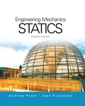
Chapter 2, Problem 2.70P
If the couple applied to the steering wheel is to have the magnitude
Expert Solution & Answer

Trending nowThis is a popular solution!

Students have asked these similar questions
The state of stress at a point is σ = -4.00 kpsi, σy = 16.00 kpsi, σ = -14.00 kpsi, Try = 11.00 kpsi,
Tyz = 8.000 kpsi, and T = -14.00 kpsi.
Determine the principal stresses.
The principal normal stress σ₁ is determined to be [
The principal normal stress σ2 is determined to be [
The principal normal stress σ3 is determined to be
kpsi.
kpsi.
The principal shear stress 71/2 is determined to be [
The principal shear stress 7½ is determined to be [
The principal shear stress T₁/, is determined to be [
kpsi.
kpsi.
kpsi.
kpsi.
Repeat Problem 28, except using a shaft that is rotatingand transmitting a torque of 150 N * m from the left bearing to the middle of the shaft. Also, there is a profile keyseat at the middle under the load.
(I want to understand this problem)
Prob 2.
The material distorts into the dashed position
shown. Determine the average normal strains &x, Ey
and the shear strain Yxy at A, and the average
normal strain along line BE.
50 mm
B
200 mm
15 mm
30 mm
D
ΕΙ
50 mm
x
A
150 mm
F
Chapter 2 Solutions
International Edition---engineering Mechanics: Statics 4th Edition
Ch. 2 - Â Which of the force system shown are equivalent...Ch. 2 - Two men are trying to roll the boulder by applying...Ch. 2 - The magnitudes of the three forces applied to the...Ch. 2 - Replace the three forces by a single equivalent...Ch. 2 - Replace the three forces with a single equivalent...Ch. 2 - The forces P1=110lb,P2=200lb, and P3=150lb are...Ch. 2 - Determine the magnitudes of the three forces...Ch. 2 - The magnitudes of the three forces acting on the...Ch. 2 - Determine the three forces acting on the plate...Ch. 2 - The force R is the resultant of the forces P1,P2,...
Ch. 2 - Knowing that the resultant of the two forces is...Ch. 2 - Knowing that the forces P and Q are equivalent to...Ch. 2 - Three ropes support the weight at A. The tension...Ch. 2 - Find the forces Q1,Q2, and Q3 so that the two...Ch. 2 - The man exerts a force P of magnitude 40 1b on the...Ch. 2 - The three forces acting on the beam can be...Ch. 2 - The trapdoor is held in the horizontal plane by...Ch. 2 - Replace the three forces acting on the guy wires...Ch. 2 - The horizontal boom carries the weight W=108lb at...Ch. 2 - The three forces, each of magnitude F, are applied...Ch. 2 - Determine the resultant force R that is equivalent...Ch. 2 - Determine the magnitude and sense of the moment of...Ch. 2 - Find the magnitude and sense of the moment of the...Ch. 2 - Two forces of magnitude P each act on the beam....Ch. 2 - A force P in the xy-plane acts on the triangular...Ch. 2 - A force P in the xy-plane acts on the triangular...Ch. 2 - Determine the moment of the force F=9i+18jlb about...Ch. 2 - Given that T=43kN and W=38kN, determine the...Ch. 2 - A moment of 50lbft about O is required to loosen...Ch. 2 - Determine the moment of the force F about point A...Ch. 2 - The resultant of the two forces shown has a line...Ch. 2 - The tow truck's front wheels will be lifted off...Ch. 2 - The force F acts on the gripper of the robot arm....Ch. 2 - Given that the magnitude of the moment of P about...Ch. 2 - The magnitude of the force P is 160 N. Determine...Ch. 2 - The magnitude of the force Q Determine the moments...Ch. 2 - The magnitude of the moment of force P about point...Ch. 2 - The magnitude of the force P is 50 kN. Determine...Ch. 2 - Determine the combined moment of the two forces...Ch. 2 - Find the combined moment of the forces P and Q...Ch. 2 - The wrench is used to tighten a nut on the wheel....Ch. 2 - The magnitudes of the two forces shown are P=16lb...Ch. 2 - The moment of the force F=50i100j70klb about point...Ch. 2 - Determine the magnitude of the moment of the 150-N...Ch. 2 - The combined moment of the two forces, each of...Ch. 2 - The force F=2i12j+5klb acts along the line AB....Ch. 2 - Calculate the combined moment of the three forces...Ch. 2 - Determine the moment of the force F=40i+30j+20kkN...Ch. 2 - Determine the moment of the 400-lb force about...Ch. 2 - The magnitude of the force F is 55 lb. Calculate...Ch. 2 - The force F=18i12j+10kN is applied to the gripper...Ch. 2 - The legs of the tripod have equal lengths. The...Ch. 2 - Determine the moment of the force F=40i8j+5kN...Ch. 2 - To lift the table without tilting, the combined...Ch. 2 - The combined moment of the three forces is zero...Ch. 2 - The trap door is held open by the rope AB. If the...Ch. 2 - The forces P and Q act on the handles of the...Ch. 2 - The magnitude of the force P is 360 N. Determine...Ch. 2 - The combined moment of P and the 20-lb force about...Ch. 2 - Determine the magnitude of the force F given that...Ch. 2 - The force F of magnitude 200Â NÂ isÂ...Ch. 2 - Calculate the moment of the force P about the axis...Ch. 2 - The force systems in Figs. (a) and (b) have the...Ch. 2 - The force F=F(0.6i+0.8j)kN is applied to the frame...Ch. 2 - Determine the combined moment of the four forces...Ch. 2 - The flexible shaft AB of the wrench is bent into a...Ch. 2 - The magnitude of the force F is 180 lb. Find the...Ch. 2 - Which of the systems are equivalent to the couple...Ch. 2 - Which of the systems are equivalent to the couple...Ch. 2 - If the couple applied to the steering wheel is to...Ch. 2 - Determine the magnitude of the couple shown.Ch. 2 - Determine the couple-vector that is equivalent to...Ch. 2 - Calculate the combined moment of the couple C and...Ch. 2 - Determine the couple-vector that is equivalent to...Ch. 2 - The two forces of magnitude F=30kN form a couple....Ch. 2 - The couple acts on the handles of a steering...Ch. 2 - The force system acting on the plate is equivalent...Ch. 2 - A couple of magnitude 3601b ft is applied about...Ch. 2 - The arm ABCD of the industrial robot lies in a...Ch. 2 - The figure shows one-half of a universal coupling...Ch. 2 - The steering column of the rack-and-pinion...Ch. 2 - Which of the systems are equivalent to the...Ch. 2 - A 15-lb force acts at point A on the high-pressure...Ch. 2 - The bracket, which is fastened to a wall by anchor...Ch. 2 - Replace the three forces applied to the beam by an...Ch. 2 - Replace the two forces shown by a force-couple...Ch. 2 - The figure shows a schematic of a torsion-bar...Ch. 2 - Replace the 250-N force with an equivalent...Ch. 2 - The magnitude of the force F acting at point A on...Ch. 2 - Replace the force-couple system acting on the pipe...Ch. 2 - (a) Replace the force F=2800i+1600j+3000klb acting...Ch. 2 - Determine the force-couple system, with the force...Ch. 2 - Replace the force F and the couple C with an...Ch. 2 - The moment of the force P about the axis AB is...Ch. 2 - Replace the force and the couple shown with an...Ch. 2 - The tensions in the cables supporting the pole are...Ch. 2 - The force acting at A is F=10i+20j5kkN. Knowing...Ch. 2 - The magnitude of the moment of the force P about...Ch. 2 - Calculate the couple-vector formed by the two...Ch. 2 - The magnitudes of the force P and couple C are...Ch. 2 - The resultant force of the three cable tensions...Ch. 2 - The force-couple system shown is equivalent to the...Ch. 2 - Replace the two forces shown with an equivalent...Ch. 2 - The three forces of magnitude P can be replaced by...Ch. 2 - Knowing that the two forces shown can be replaced...Ch. 2 - The trapdoor is held in the position shown by two...Ch. 2 - The force system consists of the force...Ch. 2 - The force system shown can be replaced with a...
Knowledge Booster


Learn more about
Need a deep-dive on the concept behind this application? Look no further. Learn more about this topic, mechanical-engineering and related others by exploring similar questions and additional content below.Similar questions
- Prob 3. The triangular plate is fixed at its base, and its apex A is given a horizontal displacement of 5 mm. Determine the shear strain, Yxy, at A. Prob 4. The triangular plate is fixed at its base, and its apex A is given a horizontal displacement of 5 mm. Determine the average normal strain & along the x axis. Prob 5. The triangular plate is fixed at its base, and its apex A is given a horizontal displacement of 5 mm. Determine the average normal strain &x along the x' axis. x' 45° 800 mm 45° 45% 800 mm 5 mmarrow_forwardAn airplane lands on the straight runaway, originally travelling at 110 ft/s when s = 0. If it is subjected to the decelerations shown, determine the time t' needed to stop the plane and construct the s -t graph for the motion. draw a graph and show all work step by steparrow_forwarddny dn-1y dn-1u dn-24 +a1 + + Any = bi +b₂- + +bnu. dtn dtn-1 dtn-1 dtn-2 a) Let be a root of the characteristic equation 1 sn+a1sn- + +an = : 0. Show that if u(t) = 0, the differential equation has the solution y(t) = e\t. b) Let к be a zero of the polynomial b(s) = b₁s-1+b2sn−2+ Show that if the input is u(t) equation that is identically zero. = .. +bn. ekt, then there is a solution to the differentialarrow_forward
- B 60 ft WAB AB 30% : The crane's telescopic boom rotates with the angular velocity w = 0.06 rad/s and angular acceleration a = 0.07 rad/s². At the same instant, the boom is extending with a constant speed of 0.8 ft/s, measured relative to the boom. Determine the magnitude of the acceleration of point B at this instant.arrow_forwardThe motion of peg P is constrained by the lemniscate curved slot in OB and by the slotted arm OA. (Figure 1) If OA rotates counterclockwise with a constant angular velocity of 0 = 3 rad/s, determine the magnitude of the velocity of peg P at 0 = 30°. Express your answer to three significant figures and include the appropriate units. Determine the magnitude of the acceleration of peg P at 0 = 30°. Express your answer to three significant figures and include the appropriate units. 0 (4 cos 2 0)m² B Aarrow_forward5: The structure shown was designed to support a30-kN load. It consists of a boom AB with a 30 x 50-mmrectangular cross section and a rod BC with a 20-mm-diametercircular cross section. The boom and the rod are connected bya pin at B and are supported by pins and brackets at A and C,respectively.1. Calculate the normal stress in boom AB and rod BC,indicate if in tension or compression.2. Calculate the shear stress of pins at A, B and C.3. Calculate the bearing stresses at A in member AB,and in the bracket.arrow_forward
- 4: The boom AC is a 4-in. square steel tube with a wallthickness of 0.25 in. The boom is supported by the 0.5-in.-diameter pinat A, and the 0.375-in.-diameter cable BC. The working stresses are 25ksi for the cable, 18 ksi for the boom, and 13.6 ksi for shear in the pin.Neglect the weight of the boom.1. Calculate the maximum value of P (kips) based on boom compression and the maximum value of P (kips) based on tension in the cable.2. Calculate the maximum value of P (kips) based on shear in pin.arrow_forward3: A steel strut S serving as a brace for a boat hoist transmits a compressive force P = 54 kN to the deck of a pier as shown in Fig. STR-08. The strut has a hollow square cross section with a wall thickness t =12mm and the angle θ between the strut and the horizontal is 40°. A pin through the strut transmits the compressive force from the strut to two gusset plates G that are welded to the base plate B. Four anchor bolts fasten the base plate to the deck. The diameter of the pin is 20mm, the thickness of the gusset plates is 16mm, the thickness of the base plate is 8mm, and the diameter of the anchor bolts is 12mm. Disregard any friction between the base plate and the deck.1. Determine the shear stress in the pin, in MPa and the shear stress in the anchor bolts, in MPa.2. Determine the bearing stress in the strut holes, in MPa.arrow_forward1. In the figure, the beam, W410x67, with 9 mm web thicknesssubjects the girder, W530x109 with 12 mm web thickness to a shear load,P (kN). 2L – 90 mm × 90 mm × 6 mm with bolts frame the beam to thegirder.Given: S1 = S2 = S5 = 40 mm; S3 = 75 mm; S4 = 110 mmAllowable Stresses are as follows:Bolt shear stress, Fv = 125 MPaBolt bearing stress, Fp = 510 MPa1. Determine the allowable load, P (kN), based on the shearcapacity of the 4 – 25 mm diameter bolts (4 – d1) and calculate the allowable load, P (kN), based on bolt bearing stress on the web of the beam.2. If P = 450 kN, determine the minimum diameter (mm) of 4 – d1based on allowable bolt shear stress and bearing stress of thebeam web.arrow_forward
- 6: The 6-kN load P is supported by two wooden members of 75 x 125-mm uniform cross section that are joined by the simple glued scarf splice shown.1. Calculate the normal stress in the glue, in MPa.2. Calculate the shear stress in the glue, in MPa.arrow_forwardUsing Matlab calculate the following performance characteristics for a Tesla Model S undergoing the 4506 drive cycle test Prated Trated Ebat 80kW 254 Nm 85kWh/1645kg MUEH A rwheel 0.315M 133.3 C 0.491 Ng ng 7g 8.190.315 8.19 0.315 7ed= 85% Ebpt 35-956 DRIVE AXLE Ebfb chę =85% V Minverter H/A Battery Charger En AC Pry 9) required energy output from the motor to drive this cycle Cassume no regenerative braking) b) range of the Tesla Model S for this drive cycle (assume no regenerative breaking c) estimated mpge cycle of the Tesla Model S for this drive Cassume no regenerative breaking) d) Recalculate parts abc now assuming you can regenerate returns correctly due to inefficiency. from braking. Be careful to handle the diminishing energy braking makes in terms of required e) Quantify the percentage difference that regenerative required energy, range and mpge, DI L Ta a ra OLarrow_forwardHW.5.1 Determine the vertical displacement of joint C on the truss as shown by using Castigliano's theorem. Let E = 200(109) GPa and A = 300 mm² 4 m E 20 kN 3 m 3 m B D 30 kN Carrow_forward
arrow_back_ios
SEE MORE QUESTIONS
arrow_forward_ios
Recommended textbooks for you
 International Edition---engineering Mechanics: St...Mechanical EngineeringISBN:9781305501607Author:Andrew Pytel And Jaan KiusalaasPublisher:CENGAGE L
International Edition---engineering Mechanics: St...
Mechanical Engineering
ISBN:9781305501607
Author:Andrew Pytel And Jaan Kiusalaas
Publisher:CENGAGE L
How to balance a see saw using moments example problem; Author: Engineer4Free;https://www.youtube.com/watch?v=d7tX37j-iHU;License: Standard Youtube License