Principles of Heat Transfer (Activate Learning with these NEW titles from Engineering!)
8th Edition
ISBN: 9781305387102
Author: Kreith, Frank; Manglik, Raj M.
Publisher: Cengage Learning
expand_more
expand_more
format_list_bulleted
Concept explainers
Videos
Textbook Question
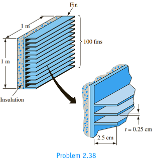
Chapter 2, Problem 2.38P
The addition of aluminum fins has been suggested to increase the rate of heat dissipation from one side ofan electronic device 1 m wide and 1 m tall. The fins are to be rectangular in cross section, 2.5 cm long and 0.25 cm thick, as shown in the figure. There are to be 100 fins per meter. The convection heat transfer coefficient, both for the wall and the fins, is estimated to be
Expert Solution & Answer

Trending nowThis is a popular solution!

Students have asked these similar questions
A bent pipe is attached to a wall with brackets as shown. A
force of F = 180 lb is applied to the end of the tube with
direction indicated by the dimensions in the figure.
Determine the support reactions at the brackets B, C, and
D. Model these brackets as journal bearings (only force
reactions perpendicular to the axis of the tube) and neglect
couple moment reactions. Assume the distance between the
supports at B and C and the tube bends nearby are
negligible such that the support at C is directly above the
support at D and the dimension g gives the distance between
supports B and C. Enter your answers in Cartesian
components.
2013 Michael Swanbom
cc 10
BY NC SA
g
h
א
B
8°
У
A
C
x
каж
Values for dimensions on the figure are given in the table
below. Note the figure may not be to scale.
Variable Value
a
6.72 in
b
11.8 in
с
14.8 in
d
42.0 in
h
26.6 in
g
28.0 in
→
The reaction at B is B =
lb.
The reaction at C is C =
lb.
The reaction at D is D =
lb.
+
<<
+
+
2.
+
+
557
〈ん
The force F1 = 10 kN, F2 = 10 kN, F3 = 10 kN, F4 = 5
KN are acting on the sttructure shown. Determine the forces
in the members specified below. Use positive values to
indicate tension and negative values to indicate compression.
F2
D
b
F1
F3 C
E
b
F4
b
B
F
a
G
Values for dimensions on the figure are given in the following
table. Note the figure may not be to scale.
Variable Value
a
3 m
b
4 m
The force in member BC is
KN.
The force in member BE is
KN.
The force in member EF is
KN.
h
=
The transmission tower is subjected to the forces F₁ 3.6
KN at 50° and F2 = 3.3 kN at = 35°. Determine the
forces in members BC, BP, PQ, PC, CD, DP and NP.
Use positive values to indicate tension and negative values to
indicate compression.
不
кажаж в *а*аж
E
N
M
d
d
IF, c
B
CENTER
LINE
S
อ
K
F₂
Kbb
cc 10
BY NC SA
2013 Michael Swanbom
Values for dimensions on the figure are given in the following
table. Note the figure may not be to scale.
Variable
Value
a
1.7 m
b
4.9 m
с
3 m
d
5.2 m
h
8.4 m
Values for dimensions on the figure are given in the following
table. Note the figure may not be to scale.
Variable Value
a
1.7 m
4.9 m
с
3 m
d
5.2 m
h
8.4 m
The force in member BC is
KN.
The force in member BP is
KN.
The force in member PQ is
KN.
The force in member PC is
KN.
The force in member CD is
KN.
The force in member DP is
KN.
The force in member NP is
KN.
Chapter 2 Solutions
Principles of Heat Transfer (Activate Learning with these NEW titles from Engineering!)
Ch. 2 - A plane wall, 7.5 cm thick, generates heat...Ch. 2 -
2.2 A small dam, which is idealized by a large...Ch. 2 - 2.3 The shield of a nuclear reactor is idealized...Ch. 2 - A plane wall 15 cm thick has a thermal...Ch. 2 - 2.5 Derive an expression for the temperature...Ch. 2 - A plane wall of thickness 2L has internal heat...Ch. 2 - 2.7 A very thin silicon chip is bonded to a 6-mm...Ch. 2 - 2.9 In a large chemical factory, hot gases at 2273...Ch. 2 - 2.14 Calculate the rate of heat loss per foot and...Ch. 2 - 2.15 Suppose that a pipe carrying a hot fluid with...
Ch. 2 - Prob. 2.16PCh. 2 - Estimate the rate of heat loss per unit length...Ch. 2 - The rate of heat flow per unit length q/L through...Ch. 2 - A 2.5-cm-OD, 2-cm-ID copper pipe carries liquid...Ch. 2 - A cylindrical liquid oxygen (LOX) tank has a...Ch. 2 - Show that the rate of heat conduction per unit...Ch. 2 - Derive an expression for the temperature...Ch. 2 - Heat is generated uniformly in the fuel rod of a...Ch. 2 - 2.29 In a cylindrical fuel rod of a nuclear...Ch. 2 - 2.30 An electrical heater capable of generating...Ch. 2 - A hollow sphere with inner and outer radii of R1...Ch. 2 - 2.34 Show that the temperature distribution in a...Ch. 2 -
2.38 The addition of aluminum fins has been...Ch. 2 - The tip of a soldering iron consists of a 0.6-cm-...Ch. 2 - One end of a 0.3-m-long steel rod is connected to...Ch. 2 - Both ends of a 0.6-cm copper U-shaped rod are...Ch. 2 - 2.42 A circumferential fin of rectangular cross...Ch. 2 - 2.43 A turbine blade 6.3 cm long, with...Ch. 2 - 2.44 To determine the thermal conductivity of a...Ch. 2 - 2.45 Heat is transferred from water to air through...Ch. 2 - 2.46 The wall of a liquid-to-gas heat exchanger...Ch. 2 - Prob. 2.47PCh. 2 - The handle of a ladle used for pouring molten lead...Ch. 2 - 2.50 Compare the rate of heat flow from the bottom...Ch. 2 - 2.51 Determine by means of a flux plot the...Ch. 2 - Prob. 2.52PCh. 2 - Determine the rate of heat transfer per meter...Ch. 2 - Prob. 2.54PCh. 2 - 2.55 A long, 1-cm-diameter electric copper cable...Ch. 2 - Prob. 2.56PCh. 2 - Prob. 2.57PCh. 2 - Prob. 2.58P
Knowledge Booster


Learn more about
Need a deep-dive on the concept behind this application? Look no further. Learn more about this topic, mechanical-engineering and related others by exploring similar questions and additional content below.Similar questions
- HELP?arrow_forwardTrue and False Indicate if each statement is true or false. T/F 1. Rule #1 protects the function of assembly. T/F 2. One of the fundamental dimensioning rules requires all dimensions apply in the free-state condition for rigid parts. T/F 3. The fundamental dimensioning rules that apply on a drawing must be listed in the general notes. T/F 4. Where Rule #1 applies to a drawing, it limits the form of every feature of size on the drawing. T/F 5. Rule #1 limits the variation between features of size on a part. T/F 6. The designer must specify on the drawing which features of size use Rule #1. T/F T/F T/F 7. Rule #1 applies to nonrigid parts (in the unrestrained state). 8. A GO gage is a fixed-limit gage. 9. Rule #1 requires that the form of an individual regular feature of size is controlled by its limits of sizearrow_forwardFEAarrow_forward
arrow_back_ios
SEE MORE QUESTIONS
arrow_forward_ios
Recommended textbooks for you
 Principles of Heat Transfer (Activate Learning wi...Mechanical EngineeringISBN:9781305387102Author:Kreith, Frank; Manglik, Raj M.Publisher:Cengage Learning
Principles of Heat Transfer (Activate Learning wi...
Mechanical Engineering
ISBN:9781305387102
Author:Kreith, Frank; Manglik, Raj M.
Publisher:Cengage Learning
Understanding Conduction and the Heat Equation; Author: The Efficient Engineer;https://www.youtube.com/watch?v=6jQsLAqrZGQ;License: Standard youtube license