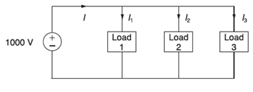
Figure 2.26 shows three loads connected in parallel across a 1 000 -V ( RMS ) , 6 0 − Hz single-phase source. Load 1: Inductive load, 125 kVA , 0. 28PF lagging. Load 2: Capacitive load, 1 0 kW , 4 0 kvar . Load 3: Resistive load, 15 kW . (a) Determine the total kW, kvar, kva, and supply power factor. (b) In order to improve the power factor to 0.8 lagging. a capacitor of negligible resistance is connected in parallel with the above loads. Find the kvar rating of that capacitor and the capacitance in μ F . Comment on the magnitude of the supply current after adding the capacitor.
Figure 2.26 shows three loads connected in parallel across a 1 000 -V ( RMS ) , 6 0 − Hz single-phase source. Load 1: Inductive load, 125 kVA , 0. 28PF lagging. Load 2: Capacitive load, 1 0 kW , 4 0 kvar . Load 3: Resistive load, 15 kW . (a) Determine the total kW, kvar, kva, and supply power factor. (b) In order to improve the power factor to 0.8 lagging. a capacitor of negligible resistance is connected in parallel with the above loads. Find the kvar rating of that capacitor and the capacitance in μ F . Comment on the magnitude of the supply current after adding the capacitor.
Figure 2.26 shows three loads connected in parallel across a
1
000
-V
(
RMS
)
,
6
0
−
Hz
single-phase source.
Load 1: Inductive load,
125 kVA
,
0.
28PF
lagging.
Load 2: Capacitive load,
1
0
kW
,
4
0
kvar
.
Load 3: Resistive load,
15
kW
.
(a) Determine the total kW, kvar, kva, and supply power factor.
(b) In order to improve the power factor to 0.8 lagging. a capacitor of negligible resistance is connected in parallel with the above loads. Find the kvar rating of that capacitor and the capacitance in
μ
F
.
Comment on the magnitude of the supply current after adding the capacitor.
f. The figure below shows two stage RC coupled amplifier. If the input resistance Rin
of each stage is 1kN. (B = 100). Determine its overall voltage gain. (5 marks)
+15V
ΣΚΩ
kn
10kΩ
10ΚΩ
output
35 ΚΩ
2ΚΩ
5kЛ
2ΚΩ
NO AI PLEASE
Chapter 2 Solutions
MindTap Engineering for Glover/Overbye/Sarma's Power System Analysis and Design, 6th Edition, [Instant Access], 1 term (6 months)
Need a deep-dive on the concept behind this application? Look no further. Learn more about this topic, computer-science and related others by exploring similar questions and additional content below.
![MindTap Engineering for Glover/Overbye/Sarma's Power System Analysis and Design, 6th Edition, [Instant Access], 1 term (6 months)](https://s3.amazonaws.com/compass-isbn-assets/textbook_empty_images/large_textbook_empty.svg)


 Power System Analysis and Design (MindTap Course ...Electrical EngineeringISBN:9781305632134Author:J. Duncan Glover, Thomas Overbye, Mulukutla S. SarmaPublisher:Cengage Learning
 Electricity for Refrigeration, Heating, and Air C...Mechanical EngineeringISBN:9781337399128Author:Russell E. SmithPublisher:Cengage Learning