
Concept explainers
Videos
Reduce each of the networks shown in Figure P2.1 to a single equivalent resistance by combining resistances in series and parallel.
* Denotes that answers are contained in the Student Solutions flies. See Appendix E for more information about accessing the Student Solutions
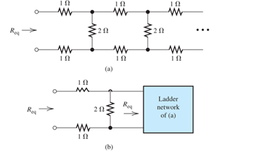
FIgure P2.1
(a)
The equivalent resistance by combining resistance in series.
Answer to Problem 2.1P
The value of equivalent resistance is
Explanation of Solution
Calculation:
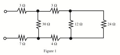
The required diagram is shown in Figure 1.
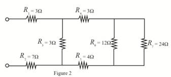
Mark the resistance
The required diagram is shown in Figure 2.
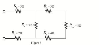
The value of resistance
Substitute
The required diagram is shown in Figure 3.
The value of resistance
Substitute
The required diagram is shown in Figure 4.
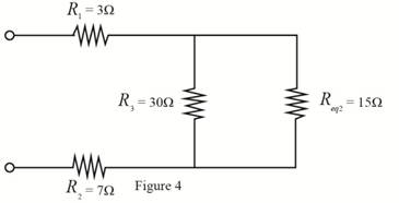
The value of resistance
Substitute
The required diagram is shown in Figure 5.
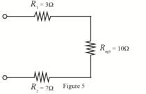
The value of resistance
Substitute
The required diagram is shown in Figure 6.
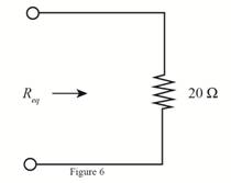
Conclusion:
Therefore, the value of equivalent resistance is
(b)
The equivalent resistance by combining resistance in series.
Answer to Problem 2.1P
The value of equivalent resistance is
Explanation of Solution
Calculation:
The required diagram is shown in Figure 7.
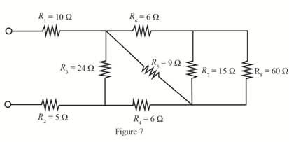
The value of resistance
Substitute
The required diagram is shown in Figure 8.
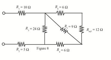
The value of resistance
Substitute
The equivalent resistance is shown in Figure 9.
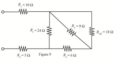
The value of resistance
Substitute
The required diagram is shown in Figure 10.
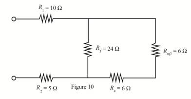
The value of resistance
Substitute
The equivalent resistance is shown in Figure 11.
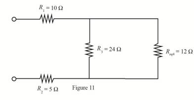
The value of resistance
Substitute
The required diagram is shown in Figure 12.
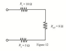
The value of resistance
Substitute
The required diagram is shown in Figure 13.
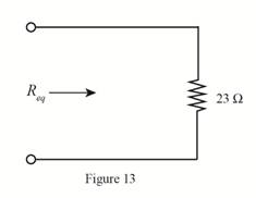
Conclusion:
Therefore, the value of equivalent resistance is
Want to see more full solutions like this?
Chapter 2 Solutions
Electrical Engineering: Principles & Applications (7th Edition)


- A single tone is modulated using FM transmitter. The SNR; at the input of the demodulator Is 20 dB. If the maximum frequency of the modulating signal is 4 kHz, and the maximum frequency deviation is 12 kHz, find the SNR, and the bandwidth (using Carson rule) at the following conditions: 1. For the given values of fm and Af. 2. If the amplitude of the modulating signal is increased by 80%. 3. If the amplitude of the modulating signal is decreased by 50%, and frequency of modulating signal is increased by 50%.arrow_forwardFM station of 100 MHz carrier frequency modulated by a 20 kHz sinusoid with an amplitude of 10 volt, so that the peak frequency deviation is 25 kHz determine: 1) The BW of the FM signal. 2) The approximated BW if the modulating signal amplitude is increased to 50 volt. 3) The approximated BW if the modulating signal frequency is increased by 70%. 4) The amplitude of the modulating signal if the BW is 65 kHz.arrow_forwardb) The joint probability function for the random variables X and Y is given in Table below. Find a) the marginal probability function of X and Y. P(Y/X) and P(X/Y). c) P(X ≥ 2, Y ≤ 2) y 1 2 3 10.05 0.05 0.1 P(X, Y) = X 20.05 0.1 0.35 3 0 0.2 0.1arrow_forward
- Suppose a random variable X as pmf / Px (x) = { %, x = 1, 2, 3, 0, otherwise. find constand c ①P(X = 1), P(X 7,2), PC1 3) C CDFarrow_forwardSuppose that a coin is tossed three so that the sample space is Let X represent the number of heads that can come up. i) Find the probability function corresponding to the random variable X. Assuming that the coin is fair ii) Find the distribution function for the random variable X. iii) Obtain its graph.arrow_forwardQ9 A single-phase transformer, 2500 / 250 V, 50 kVA, 50 Hz has the following parameters, the Primary and secondary resistances are 0.8 ohm and 0.012 ohm respectively, the primary and secondary reactance are 4 ohm and 0.04 ohm respectively and the transformer gives 96% maximum efficiency at 75% full-load. The magnetizing component of-load current is 1.2 A on 2500 V side. 1- Draw the equivalent circuit referred to primary (H.V side) and inserts all the values in it 2- Find out Ammeter, voltmeter and wattmeter readings on open-circuit and short-circuit test. If supply is given to 2500 V side in both cases. Ans. O.C. Test (Vo= 2500 V, lo=1.24 A, Wo=781.25 w) S.C. Test (Vsc =164.924 V, Isc =20 A, Wsc =800 w )arrow_forward
- Q2-A)- Enumerate the various losses in transformer. Explain how each loss varies with (Load current, supply voltage). B)- Draw the pharos diagram at load on primary side.arrow_forwardQ2- What are the parameters and loss that can be determined during open-circuit test of singlephase transformer. Draw the circuit diagram of open-circuit test and explain how can you calculate the Parameters and loss.arrow_forwardQ2-Drive the condition of maximum efficiency of single-phase transformer. Q1- A 5 KVA, 500/250 V ,50 Hz, single phase transformer gave the following reading: O.C. Test: 250 V,2 A, 50 W (H.V. side open) S.C. Test: 25 V10 A, 60 W (L.V. side shorted) Determine: i) The efficiency on full load, 0.8 lagging p.f. ii) Draw the equivalent circuit referred to primary and insert all the values it.arrow_forward
- Q2- Describe various losses in transformer. Explain how each loss varies with load current, supply voltagearrow_forwardQ1-A 12 KVA, 440/ 220 V, 50 Hz single phase transformer has 275 secondary turns. The no load current of transformer is 2A at power factor 0.375 when connected to 220 V, 50 Hz supply. The full load copper loss is 198.3 watt. Calculate a) Maximum value of flux in the core. b) Maximum efficiency at 0.8 lagging p.f c) KVA supply at maximum efficiencyarrow_forwardQ1- A 5 KVA, 240/120 volt, single-phase transformer supplies rated current to a load at 120 V. Determine the magnitude of the load impedance as seen from the input terminals of the transformer. Ans. 11.52arrow_forward
 Delmar's Standard Textbook Of ElectricityElectrical EngineeringISBN:9781337900348Author:Stephen L. HermanPublisher:Cengage Learning