Concept explainers
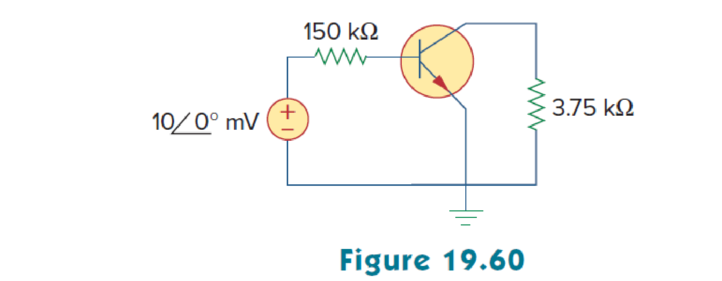
For the transistor amplifier of Fig. 19.60, find the voltage gain, current gain, input impedance, and output impedance. Assume that

Want to see the full answer?
Check out a sample textbook solution
Chapter 19 Solutions
Fundamentals of Electric Circuits
Additional Engineering Textbook Solutions
Thermodynamics: An Engineering Approach
Vector Mechanics For Engineers
Vector Mechanics for Engineers: Statics and Dynamics
Experiencing MIS
Elementary Surveying: An Introduction To Geomatics (15th Edition)
Automotive Technology: Principles, Diagnosis, And Service (6th Edition) (halderman Automotive Series)
- Find the mathematical expression in fourier series for this output below shown in the image. This must have the terms ao, ak and bkarrow_forwardPlease solve this question step by step handwritten solution and do not use ai or chat gpt please thank youarrow_forwardPlease solve this question step by step hand written solution and do not use ai or chat gpt thank youarrow_forward
- Please solve this question handwritten, step by step showing details and no ai or chat gpt solution please thank youarrow_forwardPlease explain each quations, I'll give positive feedback. For the graphs, please draw what it looks likearrow_forwardplease explain all steps and draw any drawings, don't just explain what they look like please. thank youarrow_forward
- please explain and show all steps, thank you.arrow_forwardA rectangular waveguide with dimensions a = 2.5 cm, b = 1 cm is to operate at 15 GHz. σ = 0, E4, μ= 1 3- Calculate phase constant for TE10 mode. 4- Calculate the phase velocity and wave impedance for the same mode.arrow_forwardFind v(t) for t> 0 in the circuit of Fig. below. Assume the switch has been open for a long time and is closed at t = 0. Calculate v (t) at t = 0.5. 10 V 202 www +21 t=0 60 ww 13 F بلا SVarrow_forward
- Q: A rectangular waveguide with dimensions a = 2.5 cm, b = 1 cm is to operate at 15 GHz. σ = 0, E4, μ = 1 1- At which frequencies this type of TL (transmission line) operate ? 2- Why this this type is used in such frequencies? 3- Calculate phase constant for TE10 mode. 4- Calculate the phase velocity and wave impedance for the same mode.arrow_forwardK Q1/ For the system G(s)= (s+2)(s+4)(s+5) H(s)=1 a. Draw the Bode log-magnitude and phase plots. b. Find the range of K for stability from your Bode plots. c. Evaluate gain margin, phase margin, zero dB frequency, and 180° frequency from your Bode plots for K = 200arrow_forwardQ3/A unity-feedback system with the forward transfer function S(S+7) is operating with a closed-loop step response that has 15% overshoot. Do the following: a. Evaluate the settling time. b. Design a PD compensator to decrease the settling time by three times.arrow_forward
 Introductory Circuit Analysis (13th Edition)Electrical EngineeringISBN:9780133923605Author:Robert L. BoylestadPublisher:PEARSON
 Delmar's Standard Textbook Of ElectricityElectrical EngineeringISBN:9781337900348Author:Stephen L. HermanPublisher:Cengage Learning
 Programmable Logic ControllersElectrical EngineeringISBN:9780073373843Author:Frank D. PetruzellaPublisher:McGraw-Hill Education
 Fundamentals of Electric CircuitsElectrical EngineeringISBN:9780078028229Author:Charles K Alexander, Matthew SadikuPublisher:McGraw-Hill Education
 Electric Circuits. (11th Edition)Electrical EngineeringISBN:9780134746968Author:James W. Nilsson, Susan RiedelPublisher:PEARSON
 Engineering ElectromagneticsElectrical EngineeringISBN:9780078028151Author:Hayt, William H. (william Hart), Jr, BUCK, John A.Publisher:Mcgraw-hill Education,


