
Calculate the voltage gain, current gain, input impedance, and output impedance for the transistor network shown in Figure 19.132 in the textbook.
Answer to Problem 93P
The voltage gain, current gain, input impedance, and output impedance for the transistor network are
Explanation of Solution
Given Data:
Refer to Figure 19.132 in the textbook for the transistor network circuit.
From the given transistor network circuit, the internal resistance
Formula used:
Refer to Equation 19.73 in the textbook and write the expression for voltage gain of a transistor network in terms of hybrid parameters as follows:
Here,
Write the expression for current gain of the transistor network as follows:
Here,
Write the expression for input impedance of the transistor network as follows:
Calculation:
Redraw the given circuit as shown in Figure 1.
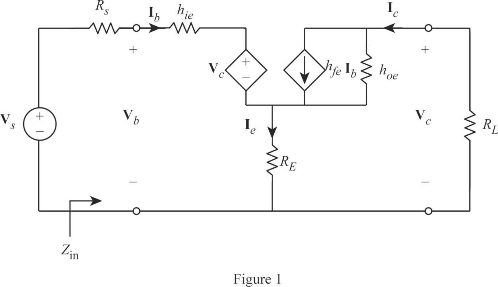
From Figure 1, write the expression for emitter current as follows:
Write the expression for base voltage from the circuit in Figure 1 as follows:
Write the expression for collector current as follows:
Write the expression for collector voltage as follows:
From Equation (7), substitute
Rearrange the expression as follows:
From Equation (2), substitute
Substitute 150 for
From Equation (6), substitute
Rearrange the expression as follows:
Rearrange the expression in Equation (5) as follows:
From Equations (7) and (9), substitute
Rearrange the expression as follows:
Substitute 150 for
Simplify the expression as follows:
From Equation (1), substitute
From Equation (9), substitute
Rearrange the expression as follows:
Substitute 150 for
From Equation (3), substitute
Consider output voltage
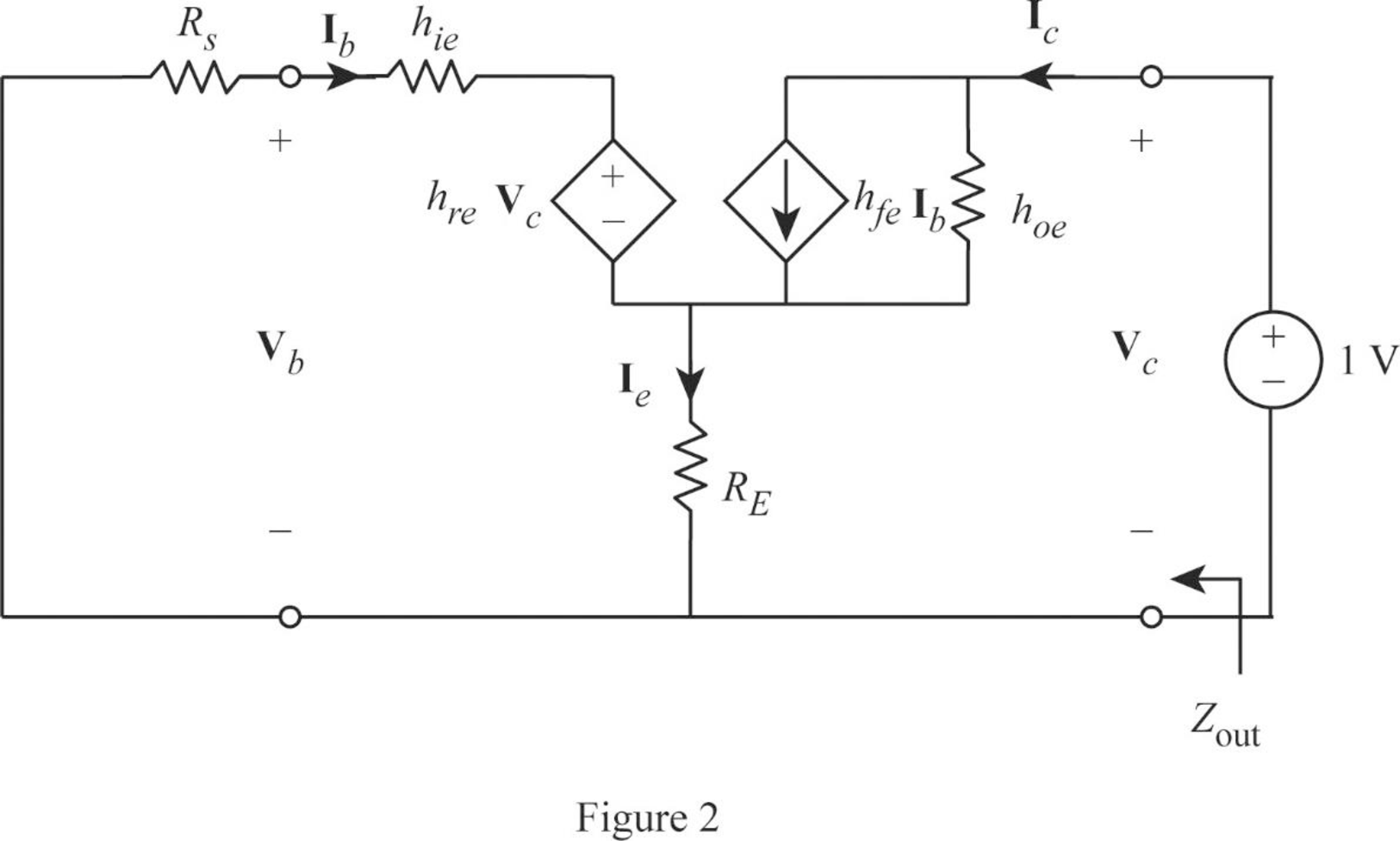
Apply KVL to the input loop for the circuit in Figure 2 as follows:
Substitute 1 for
Apply KCL at the output node for the circuit in Figure 2 as follows:
Substitute 1 for
Rearrange the expression as follows:
From Equation (12), substitute
Substitute 150 for
Write the expression for output impedance of the transistor network as follows:
Substitute 1 for
Conclusion:
Thus, the voltage gain, current gain, input impedance, and output impedance for the transistor network are
Want to see more full solutions like this?
Chapter 19 Solutions
EE 98: Fundamentals of Electrical Circuits - With Connect Access

- 3. Roughly sketch the root locus for the following locations of open-loop poles and zeros. You just need to show the shape of the root locus; you do not calculate the asymptote, break-in, and break-away points. ☑ (a) (b) ☑ Φ ① $3 (c)arrow_forwardDO NOT WANT AI WILL REJECTarrow_forwardDO NOT NEED AI WILL REJECTarrow_forward
- S+4 4. Sketch the root locus for L(s) = (s+6) (s+1)2 using rules 1, 2, and 3. For rule 3, you need to find the value of σ and a for the asymptotes. From the root-locus, explain why the closed-loop system is always stable for any choice of the design parameter K in the range 0 < K < ∞o.arrow_forward2. Consider the following system. K(s+3) (s+4) (s+1)(s+2) Check whether the points below are in the root locus. If the point is in the root locus, then also find what the corresponding gain K. i) ii) -2+j3 -2+1√ √ Hint: First find L(s). Next, in L(s) replace s with the value of the point and then express it in polar format r20 using calculator. The point will be in the root locus if and only if = 180° or odd multiple of 180°. When the point is in the root locus, the corresponding gain K is obtained as K ==arrow_forwardsolve and show workarrow_forward
- Design and find values. please solve ASAP (it's for practice before an exma, I don't have time)arrow_forwardCan you show why the answer is that for this question using second order differential equations, instead of laplace transformsarrow_forward2. For each of the following transfer functions, G(s) = Y(s)/U(s), find the differential equation relating the input u(t) to the output y(t). (s+2)(s+3) (a) G(s) = (s+1)(s+4) (s²+0.4s+1.04) (s+3) (b) G(s)= (s2+0.2s+1)(s+2)(s+4)arrow_forward
 Introductory Circuit Analysis (13th Edition)Electrical EngineeringISBN:9780133923605Author:Robert L. BoylestadPublisher:PEARSON
 Delmar's Standard Textbook Of ElectricityElectrical EngineeringISBN:9781337900348Author:Stephen L. HermanPublisher:Cengage Learning
 Programmable Logic ControllersElectrical EngineeringISBN:9780073373843Author:Frank D. PetruzellaPublisher:McGraw-Hill Education
 Fundamentals of Electric CircuitsElectrical EngineeringISBN:9780078028229Author:Charles K Alexander, Matthew SadikuPublisher:McGraw-Hill Education
 Electric Circuits. (11th Edition)Electrical EngineeringISBN:9780134746968Author:James W. Nilsson, Susan RiedelPublisher:PEARSON
 Engineering ElectromagneticsElectrical EngineeringISBN:9780078028151Author:Hayt, William H. (william Hart), Jr, BUCK, John A.Publisher:Mcgraw-hill Education,