
Concept explainers
Videos
Determine the z parameters for the network in Fig. 19.118.
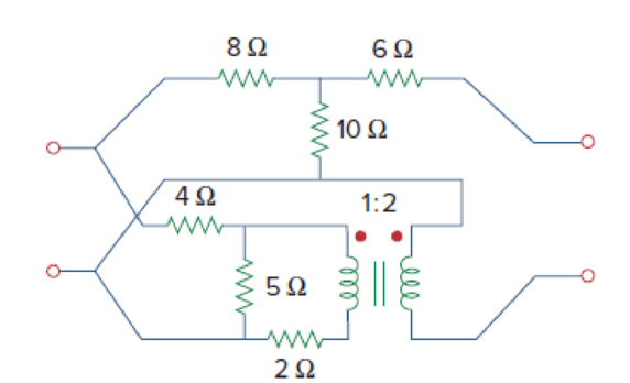
Figure 19.118
Find the impedance parameters for the given two-port network in Figure 19.118 in the textbook.
Answer to Problem 71P
The impedance parameters for the given two-port network are
Explanation of Solution
Given Data:
Refer to Figure 19.118 in the textbook for the given two-port network.
Formula used:
Write the expressions for transmission (ABCD) parameters of a two-port network as follows:
Refer to Figure 19.106 in the textbook and write the expression for transmission parameters for a T-network as follows:
Refer to TABLE 19.1 in the textbook, write the expression for g parameters in terms of transmission parameters as follows:
Write the expression for
From TABLE 19.1 in the textbook, write the expression for impedance parameters in terms of g parameters as follows:
Write the expression for
Calculation:
The given interconnected network is a series-parallel combination of two two-port networks. Find g parameters for each network and add them for overall g parameters of entire network. And then convert the overall g parameters into z parameters.
Consider upper network (T-network) as network
Compare upper network with the Figure 19.106 in the textbook and write the resistance values as follows:
Substitute
Convert the obtained transmission parameters into g parameters as follows:
Substitute 1.8 for
Substitute 1.8 for
As the lower network is a series combination of resistive network and transformer, find the transmission parameters for each network and product them to get the transmission parameters for lower network.
Consider resistive network as
Find the transmission parameters for network
The transmission parameters
Redraw the network
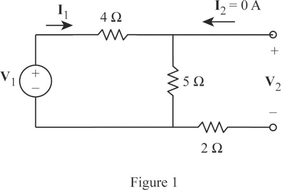
From Figure 1, write the expression for
Rearrange the expression as follows:
Substitute 1.8 for
From Figure 1, write the expression for
Substitute
Rearrange the expression as follows:
Substitute
The transmission parameters
Rearrange the expression as follows:
Redraw the network
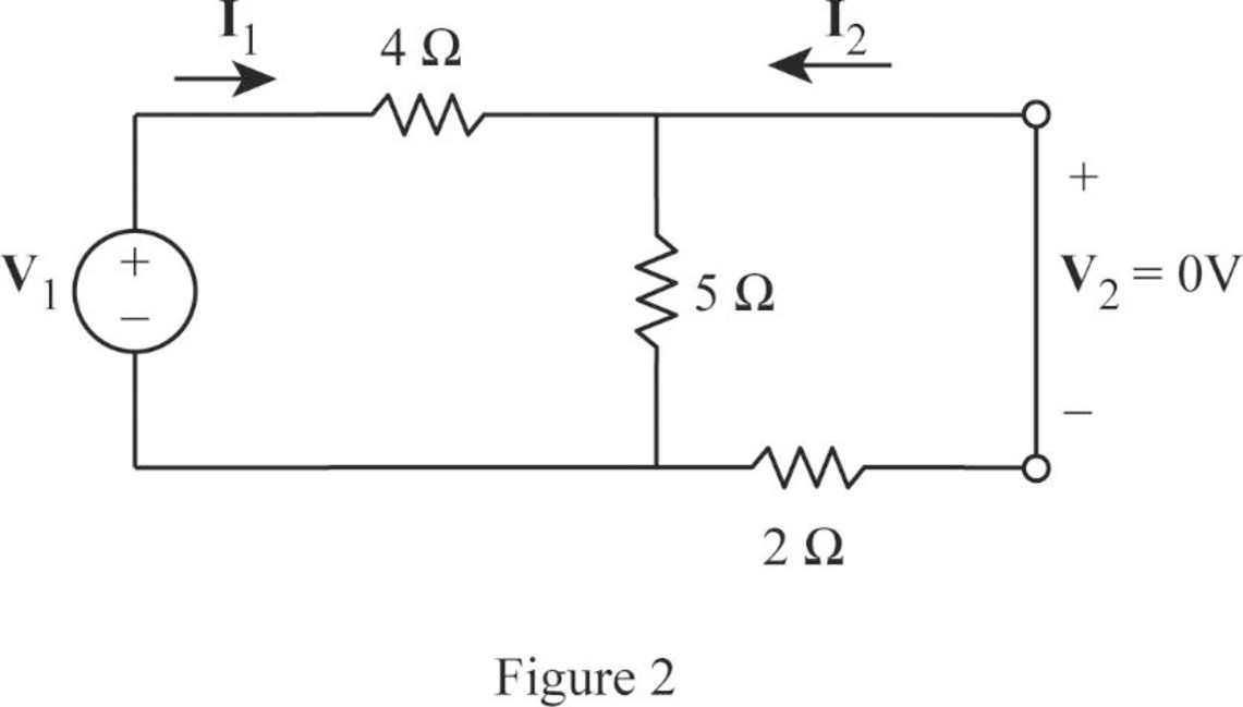
From Figure 2, write the expression for
Rearrange the expression as follows:
Substitute
From Figure 2, write the expression for
From Equation (13), substitute
From the calculations, write the transmission parameters for the network
Find the transmission parameters for network
From the given transformer network
Rearrange the expression as follows:
From the given transformer network
Rearrange the expression as follows:
Compare Equation (14) with Equation (1) and obtain the parameters
Compare Equation (15) with Equation (2) and obtain the parameters
From the calculations, write the transmission parameters for the network
As the networks
Substitute
Convert the obtained transmission parameters into g parameters for lower network as follows:
Substitute 0.9 for
Substitute 0.9 for
Write the expression for overall g parameters for the given network as follows:
Substitute
Convert the obtained g parameters into impedance parameters to attain the required objective.
Substitute
Substitute
Conclusion:
Thus, the impedance parameters for the given two-port network are
Want to see more full solutions like this?
Chapter 19 Solutions
EE 98: Fundamentals of Electrical Circuits - With Connect Access


- Q5B. Find the type of the controller in the following figures and use real values to find the transfer function of three of them[ Hint Pi,Pd and Lead,lag are found so put the controller with its corresponding compensator]. R₁ R₂ Rz HE C2 RA HE R₁ R2 RA とarrow_forwardQ1// Sketch the root locus for the unity feedback system. Where G(s)=)= K S3+252 +25 and find the following a. Sketch the asymptotes b. The exact point and gain where the locus crosses the jo-axis c. The breakaway point on the real axis d. The range of K within which the system is stable e. Angles of departure and arrival.arrow_forwardDetermine X(w) for the given function shown in Figure (1) by applying the differentiation property of the Fourier Transform. Figure (1) -1 x(t)arrow_forward
- Can you solve a question with a drawing Determine X(w) for the given function shown in Figure (1) by applying the differentiation property of the Fourier Transform. Figure (1) -1 x(t)arrow_forwardAn inductor has a current flow of 3 A when connected to a 240 V, 60 Hz power line. The inductor has a wire resistance of 15 Find the Q of the inductorarrow_forwardصورة من s94850121arrow_forward
- The joint density function of two continuous random variables X and Yis: p(x, y) = {Keós (x + y) Find (i) the constant K 0 2 0arrow_forwardShow all the steps please, Solve for the current through R2 if E2 is replaced by a current source of 10mA using superposition theorem. R5=470Ω R2=1000Ω R6=820Ωarrow_forwardPlease solve it by explaining the steps. I am trying to prepare for my exam tomorrow, so any tips and tricks to solve similar problems are highly appreciated. Plus, this is a past exam I am using to prepare.arrow_forwardPlease solve it by explaining the steps. I am trying to prepare for my exam today, so any tips and tricks to solve similar problems are highly appreciated. Plus, this is a past exam I am using to prepare.arrow_forwardIf C is the circle |z|=4 evaluate f f (z)dz for each of the following functions using residue. 1 f(z) = z(z²+6z+4)arrow_forwardIf C is the circle |z|=4 evaluate ff(z)dz for each of the following functions using residue. f(z) z(z²+6z+4)arrow_forwardarrow_back_iosSEE MORE QUESTIONSarrow_forward_ios
 Introductory Circuit Analysis (13th Edition)Electrical EngineeringISBN:9780133923605Author:Robert L. BoylestadPublisher:PEARSON
 Delmar's Standard Textbook Of ElectricityElectrical EngineeringISBN:9781337900348Author:Stephen L. HermanPublisher:Cengage Learning
 Programmable Logic ControllersElectrical EngineeringISBN:9780073373843Author:Frank D. PetruzellaPublisher:McGraw-Hill Education
 Fundamentals of Electric CircuitsElectrical EngineeringISBN:9780078028229Author:Charles K Alexander, Matthew SadikuPublisher:McGraw-Hill Education
 Electric Circuits. (11th Edition)Electrical EngineeringISBN:9780134746968Author:James W. Nilsson, Susan RiedelPublisher:PEARSON
 Engineering ElectromagneticsElectrical EngineeringISBN:9780078028151Author:Hayt, William H. (william Hart), Jr, BUCK, John A.Publisher:Mcgraw-hill Education,