
Concept explainers
Videos
Calculate z and y parameters for the two-port network in Figure 19.78 in the textbook.
Answer to Problem 17P
The z and y parameters for the given two-port network are
Explanation of Solution
Given Data:
Refer to Figure 19.78 in the textbook for the given two-port network.
Formula used:
Write the expressions for impedance parameters of a two-port network as follows:
Refer to the TABLE 19.1 in the textbook and write the expression for admittance parameters in terms of z parameters as follows:
Write the expression for
Calculation:
The impedance parameters
Draw the given circuit as shown in Figure 1 to obtain the parameters
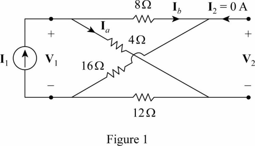
In Figure 1,
From Equation (5),
From Figure 1, write the expression for
From Figure 1, write the expression for
From Figure 1, write the expression for
Substitute
Rearrange the expression as follows:
Substitute
The impedance parameters
Draw the given circuit as shown in Figure 2 to obtain the parameters
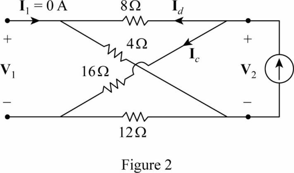
In Figure 2,
From Equation (8),
From Figure 2, write the expression for
From Figure 2, write the expression for
From Figure 2, write the expression for
Substitute
Rearrange the expression as follows:
Substitute
From the analysis, the impedance parameters for the given two-port network are written as follows:
Convert the obtained z parameters into admittance parameters to obtain the admittance parameters for the given two-port network.
Substitute
Substitute
Conclusion:
Thus, the z and y parameters for the given two-port network are
Want to see more full solutions like this?
Chapter 19 Solutions
EE 98: Fundamentals of Electrical Circuits - With Connect Access


- Don't use ai to answer I will report you answerarrow_forward.I need in the way of spaces and not in shortened ways A 3-phase, 50 Hz, 132 kV overhead line transpose system of bundle conductors .a radius of conductor is 0.5 cm Calculate the total inductance of the line.) bi 4m C1 al 4m m birarrow_forward1B) Suppose the flip-flops are 74F74 devices and the AND gates are 74F08 devices. Let maxtpd,D=9ns, maxtsu,D=3ns, and maxtpd,AND=6ns. What is the maximum clock frequency at which the circuit can operate reliably? 2) Compare serial transmission and parallel transmission and discuss their advantages and disadvantages. 3) Explain briefly how the slave can protect itself from being overwhelmed by the master in I2 4) A hypothetical logic family has the following specifications. VOH=4.6V VIH=4.0V VOL=0.5V VIL=1.0V IOH=-1mA IIH=50μA IOL=8mA IIL=-0.6mA (4a) What are the noise margins? (4b) What is the fan-out capability? That is, suppose all gates are chosen from the same logic family, how many gates can an output gate reliably drive? 5) Explain briefly why USB device address and…arrow_forward
- can you drow set Vi=0, set Vo=0 B. For the FET amplifier circuit of Fig.(2), determine the topolgy, and the gain without and with feedback with the following circuit values: rao, and g 4mS Is Voo 60 K www 100 K 0.25 K IK Fig.(2) 20 K ww Voarrow_forwardcan you draw acircuit For the feedback circuit shown below VDD Set Vico set Vo=0 Is 100 K 26 K 2 K Q1 76 K IF 60 K 40 K Voarrow_forwardThe previous solutions are incorrect and unclear. If possible, please solve the question on the images .clearly. Thank you A 3-phase, 50 Hz, 132 kV overhead line transpose system of bundle conductors .a radius of conductor is 0.5 cm. Calculate the total inductance of the line. bi 4m m im birarrow_forward
- A 3-phase, 50 Hz, overhead line has conductors placed in a horizontal plane as shown in the figure below. Conductor diameter is 2 cm. If the line length is 150 km, calculate the inductance, capacitance per phase of the line assuming complete transposition. a 20 cm b 20 cmarrow_forwardDon't use ai to answer I will report you answerarrow_forwardA 3-phase, 50 Hz, 132 kV overhead line transpose system of bundle conductors .a radius of conductor is 0.5 cm. Calculate the total inductance of the line. bi 4m Im cl 4m birarrow_forward
- A single phase has two group A and B, 50 Hz, overhead line system has radius of conductor 0.5 cm. Calculate the total inductance of the line 21 A a2 b₂ 4 m B b₁ 3m 6 cm 2 marrow_forwardIn a single phase below, conductors a₁ and a₂ are in parallel form one circuit while conductors b₁ and b₂ in parallel form the return path. Calculate the total inductance of the line per km assuming that current is equally shared by the two parallel conductors. Conductor diameter in 2-0 cm. a₁ az b₁ b₂ 100 cm 20 cm 20 cmarrow_forwardDon't use ai to answer I will report you answerarrow_forward
 Introductory Circuit Analysis (13th Edition)Electrical EngineeringISBN:9780133923605Author:Robert L. BoylestadPublisher:PEARSON
 Delmar's Standard Textbook Of ElectricityElectrical EngineeringISBN:9781337900348Author:Stephen L. HermanPublisher:Cengage Learning
 Programmable Logic ControllersElectrical EngineeringISBN:9780073373843Author:Frank D. PetruzellaPublisher:McGraw-Hill Education
 Fundamentals of Electric CircuitsElectrical EngineeringISBN:9780078028229Author:Charles K Alexander, Matthew SadikuPublisher:McGraw-Hill Education
 Electric Circuits. (11th Edition)Electrical EngineeringISBN:9780134746968Author:James W. Nilsson, Susan RiedelPublisher:PEARSON
 Engineering ElectromagneticsElectrical EngineeringISBN:9780078028151Author:Hayt, William H. (william Hart), Jr, BUCK, John A.Publisher:Mcgraw-hill Education,