Introductory Circuit Analysis (13th Edition)
13th Edition
ISBN: 9780133923605
Author: Robert L. Boylestad
Publisher: PEARSON
bartleby

Videos

Textbook Question
Book Icon
Chapter 19, Problem 1P

Using supeerposition, determine the current through the inductance XL for the network of Fig. 19.105.
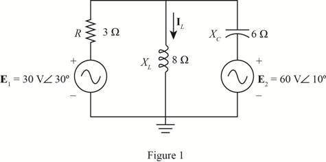
Chapter 19, Problem 1P, Using supeerposition, determine the current through the inductance XL for the network of Fig.

Expert Solution & Answer
Check Mark
To determine

The current flowing through the inductance XL of the given circuit.

Answer to Problem 1P

The current through the inductor is IL=6.132.11°A.

Explanation of Solution

Given:

The given circuit is shown in Figure 1.

Introductory Circuit Analysis (13th Edition), Chapter 19, Problem 1P , additional homework tip  1

Calculation:

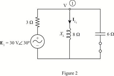
To apply superposition theorem, first consider the effect of voltage source E1 and replace the source E2 by a short circuit.

The required diagram is shown in Figure 2.
Introductory Circuit Analysis (13th Edition), Chapter 19, Problem 1P , additional homework tip  2

Let the voltage at node 1 is V. Apply KCL at node 1.

  V3030°3+Vj8+Vj6=0(13+1 j8+1 j6)V=3030°3(0.333+j0.0417)=1030°V=29.7722.87°V

The current through the inductor is given by

  IL1=Vj8

Substitute 29.7722.87° for V in the above equation.

  IL1=29.7722.87°j8=3.7267.12°A

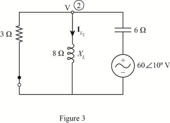
Now consider the effect of source voltage E2 and replace the source voltage E1 by short circuit.

The required diagram is shown in Figure 3.
Introductory Circuit Analysis (13th Edition), Chapter 19, Problem 1P , additional homework tip  3

Apply the KCL at node 2.

  V3+Vj8+V6010°j6=0(13+1 j8+1 j6)V=6010°j6(0.333+j0.0417)=10100°V=29.7792.87°V

The current through the inductor is given by,

  IL2=29.7792.87°j8=3.722.87°A

Therefore, according to super position theorem the current through the inductor is given by

  IL=IL1+IL2

Substitute 3.7267.12°A for IL1 and 3.722.87°A for IL2 in the above equation.

  IL=3.8767.12°+3.8792.87°IL=6.132.11°A

Conclusion:

Therefore, the current through the inductor is I=6.132.11°A.

Want to see more full solutions like this?

Subscribe now to access step-by-step solutions to millions of textbook problems written by subject matter experts!
Students have asked these similar questions
Find the step response of each of the transfer functions shown in Eqs. (4.62) through (4.64) and compare them. [Shown in the image]Book: Norman S. Nise - Control Systems Engineering, 6th EditionTopic: Chapter-4: Time Response, Example 4.8Solve the math with proper explanation. Please don't give AI response. Asking for a expert verified answer.
2. With respect to the circuit shown in Figure 2 below V2 -R1 R2 R4 w R3 R5 Figure 2: DC Circuit 2 a. Using Ohm's and Kirchhoff's laws calculate the current flowing through R3 and so determine wattage rating of R3. b. Verify your results with simulations. Note: you must use the values for the components in Table 2. Table 2 V2 (Volts) R1 (KQ) R2 (KQ) R3 (KQ) R4 (KQ) R5 (KQ) 9 3.3 5 10 6 1 3.3
Don't use ai to answer i will report your answer

Chapter 19 Solutions

Introductory Circuit Analysis (13th Edition)

Ch. 19 - Using superposition, determine the current IL for...Ch. 19 - Determine VL for the network of Fig. 19.116...Ch. 19 - Calculate the current I for the network of Fig....Ch. 19 - Find the voltage Vs for the network in Fig....Ch. 19 - Find the ThĂ©venin equivalent circuit for the...Ch. 19 - Find the Thevenin equivalent circuit for the...Ch. 19 - Find the Thevenin equivalent circuit for the...Ch. 19 - Find the Thevenin equivalent circuit for the...Ch. 19 - Find the Thevenin equivalent circuit for the...Ch. 19 - Find the Thevenin equivalent circuit for the...Ch. 19 - Find the ThĂªvenin equivalent circuit for the...Ch. 19 - Find the ThĂªvenin equivalent circuit for the...Ch. 19 - a. Find the ThĂ©venin equivalent circuit for the...Ch. 19 - a. Find the ThĂ©venin equivalent circuit for the...Ch. 19 - a. Find the ThĂ©venin equivalent circuit of the...Ch. 19 - Determine the ThĂ©venin equivalent circuit for the...Ch. 19 - Determine the ThĂ©venin equivalent circuit for the...Ch. 19 - Prob. 28PCh. 19 - Prob. 29PCh. 19 - Find the ThĂ©venin equivalent circuit for the...Ch. 19 - Determine the ThĂ©venin equivalent circuit for the...Ch. 19 - Prob. 32PCh. 19 - Find the ThĂ©venin equivalent circuit for the...Ch. 19 - Find the Norton equivalent circuit for the network...Ch. 19 - Find the Norton equivalent circuit for the network...Ch. 19 - Find the Norton equivalent circuit for the network...Ch. 19 - Find the Norton equivalent circuit for the portion...Ch. 19 - Find the Norton equivalent circuit for the portion...Ch. 19 - a. Find the Norton equivalent circuit for the...Ch. 19 - a. Find the Norton equivalent circuit for the...Ch. 19 - a. Find the Norton equivalent circuit for the...Ch. 19 - Determine the Norton equivalent circuit for the...Ch. 19 - Determine the Norton equivalent circuit for the...Ch. 19 - Find the Norton equivalent circuit for the network...Ch. 19 - Find the Norton equivalent circuit for the network...Ch. 19 - Prob. 46PCh. 19 - Prob. 47PCh. 19 - Find the load impedance ZL for the network of Fig....Ch. 19 - Find the load impedance ZL for the network of Fig....Ch. 19 - Find the load impedance ZL for the network of Fig....Ch. 19 - Find the load impedance ZL for the network of Fig....Ch. 19 - Prob. 52PCh. 19 - a. Determine the load impedance to replace the...Ch. 19 - a. Determine the load impedance to replace the...Ch. 19 - a. Determine the load impedance to replace the...Ch. 19 - Prob. 56PCh. 19 - a. For the network in Fig. 19.139, determine the...Ch. 19 - For the network in Fig. 19.140, determine two...Ch. 19 - Prob. 59PCh. 19 - Using Millmans theorem, determine the current...Ch. 19 - Prob. 61PCh. 19 - Determine the current IL for the network in Fig....Ch. 19 - Using schematics, determine V2 for the network in...Ch. 19 - Prob. 64PCh. 19 - Using schematics, plot the power to the R-C load...
Knowledge Booster
Background pattern image
Electrical Engineering
Learn more about
Need a deep-dive on the concept behind this application? Look no further. Learn more about this topic, electrical-engineering and related others by exploring similar questions and additional content below.
Recommended textbooks for you
Text book image
Electric Motor Control
Electrical Engineering
ISBN:9781133702818
Author:Herman
Publisher:CENGAGE L
Mesh Current Problems in Circuit Analysis - Electrical Circuits Crash Course - Beginners Electronics; Author: Math and Science;https://www.youtube.com/watch?v=DYg8B-ElK0s;License: Standard Youtube License