
Introductory Circuit Analysis; Laboratory Manual For Introductory Circuit Analysis Format: Kit/package/shrinkwrap
13th Edition
ISBN: 9780134297446
Author: Boylestad, Robert L.
Publisher: Prentice Hall
expand_more
expand_more
format_list_bulleted
Videos
Textbook Question
Chapter 19, Problem 14P
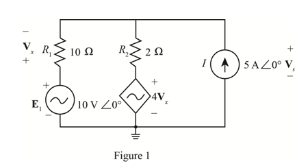
Find the voltage Vs for the network in Fig. 19.118.
Expert Solution & Answer
Want to see the full answer?
Check out a sample textbook solution
Students have asked these similar questions
Can you help with the following problems please.
Can you please help me with this problem?
Consider the following transformer circuit assuming an ideal transformer. In this circuit
the signal generator will provide a 10-Volt peak-to-peak sinusoidal signal at a frequency
of 1.0 kHz. Assume that L₁ = 0.65 H, L2 = 0.00492 H (=4.92 mH) and that the coupling
constant = 0.99925.
+
VG1(
R1 1k
N1:N2
11.5:1
12
V1 N1
N2
V2
R2 8.2
1) Find the following using the theory presented in the prelab reading:
a) Start with Equations (2) of the prelab reading and show that the input impedance
to an ideal transformer is given by the equation for Z1 (=V1/11) in Equations (4) of
the prelab reading.
Equations (2) are: V₁ = joLI₁ + jœMI₂ and V₂ = j@MI₁ +j@L₂I₂
The equation for the input impedance is: Z₁ = 1½ = jwL₁ +
(WM)²
jwL₂+ZL
b) Assuming that Z is a real impedance, find the equations for the real and
imaginary parts of Z1.
c) Use your equations from part (b) to calculate the value of the input impedance
(Z) at an operating frequency of 200 Hz. Assume that the load impedance is 8.2
Ohms…
Chapter 19 Solutions
Introductory Circuit Analysis; Laboratory Manual For Introductory Circuit Analysis Format: Kit/package/shrinkwrap
Ch. 19 - Using supeerposition, determine the current...Ch. 19 - Using superposition, determine the current through...Ch. 19 - Using superposition, determine the current IL for...Ch. 19 - Using superposition, determine the voltage across...Ch. 19 - Using superposition, determine the current through...Ch. 19 - Using superposition, find the sinusoidal...Ch. 19 - Using superposition, find the sinusoidal...Ch. 19 - Using superspostion, find the current I for the...Ch. 19 - Using superposition, determine the current IL...Ch. 19 - Using superposition, for the network of Fig....
Ch. 19 - Using superposition, determine the current IL for...Ch. 19 - Determine VL for the network of Fig. 19.116...Ch. 19 - Calculate the current I for the network of Fig....Ch. 19 - Find the voltage Vs for the network in Fig....Ch. 19 - Find the ThĂ©venin equivalent circuit for the...Ch. 19 - Find the Thevenin equivalent circuit for the...Ch. 19 - Find the Thevenin equivalent circuit for the...Ch. 19 - Find the Thevenin equivalent circuit for the...Ch. 19 - Find the Thevenin equivalent circuit for the...Ch. 19 - Find the Thevenin equivalent circuit for the...Ch. 19 - Find the ThĂªvenin equivalent circuit for the...Ch. 19 - Find the ThĂªvenin equivalent circuit for the...Ch. 19 - a. Find the ThĂ©venin equivalent circuit for the...Ch. 19 - a. Find the ThĂ©venin equivalent circuit for the...Ch. 19 - a. Find the ThĂ©venin equivalent circuit of the...Ch. 19 - Determine the ThĂ©venin equivalent circuit for the...Ch. 19 - Determine the ThĂ©venin equivalent circuit for the...Ch. 19 - Prob. 28PCh. 19 - Prob. 29PCh. 19 - Find the ThĂ©venin equivalent circuit for the...Ch. 19 - Determine the ThĂ©venin equivalent circuit for the...Ch. 19 - Prob. 32PCh. 19 - Find the ThĂ©venin equivalent circuit for the...Ch. 19 - Find the Norton equivalent circuit for the network...Ch. 19 - Find the Norton equivalent circuit for the network...Ch. 19 - Find the Norton equivalent circuit for the network...Ch. 19 - Find the Norton equivalent circuit for the portion...Ch. 19 - Find the Norton equivalent circuit for the portion...Ch. 19 - a. Find the Norton equivalent circuit for the...Ch. 19 - a. Find the Norton equivalent circuit for the...Ch. 19 - a. Find the Norton equivalent circuit for the...Ch. 19 - Determine the Norton equivalent circuit for the...Ch. 19 - Determine the Norton equivalent circuit for the...Ch. 19 - Find the Norton equivalent circuit for the network...Ch. 19 - Find the Norton equivalent circuit for the network...Ch. 19 - Prob. 46PCh. 19 - Prob. 47PCh. 19 - Find the load impedance ZL for the network of Fig....Ch. 19 - Find the load impedance ZL for the network of Fig....Ch. 19 - Find the load impedance ZL for the network of Fig....Ch. 19 - Find the load impedance ZL for the network of Fig....Ch. 19 - Prob. 52PCh. 19 - a. Determine the load impedance to replace the...Ch. 19 - a. Determine the load impedance to replace the...Ch. 19 - a. Determine the load impedance to replace the...Ch. 19 - Prob. 56PCh. 19 - a. For the network in Fig. 19.139, determine the...Ch. 19 - For the network in Fig. 19.140, determine two...Ch. 19 - Prob. 59PCh. 19 - Using Millmans theorem, determine the current...Ch. 19 - Prob. 61PCh. 19 - Determine the current IL for the network in Fig....Ch. 19 - Using schematics, determine V2 for the network in...Ch. 19 - Prob. 64PCh. 19 - Using schematics, plot the power to the R-C load...
Knowledge Booster


Learn more about
Need a deep-dive on the concept behind this application? Look no further. Learn more about this topic, electrical-engineering and related others by exploring similar questions and additional content below.Similar questions
- Use: R1 = 1.5K, R2 = 5K, R3 = 1K, R4 = 2K, R5 = 2K, R6 = 1K. 40%: Find the value for Vs (in V) such as IR2 = 1mA. 40%: Find the voltage VD. 20%: simulate the circuit in Falstad (attach the link). A 1,5k B R1 Vs L 5k P2 R2 R6 E C R3 С IR2= 1mA D H4 R4 2k 2k R5arrow_forwardThe joint pdf of random variables X=1, 2 and Y=1,2,3 is Y P(X,Y)= X [0.105 0.2 0.15] 0.151 0.18arrow_forwardFind the eigenvalues and the corresponding eigen vectors of the following matrix: -5 A = [ 21 -7 4]arrow_forward
- + 2) Acircuit is given as shown. (a) Find and label the circuit nodes (6) Determine voltages V₁, V2, V3 and Vy 4V C/E 노동 + 051 V4 + C/E + 3V- + /E5V 1 av + C E uk لا + V3C/E CIE + E6V -arrow_forwardConsider the following transformer circuit assuming an ideal transformer. In this circuit the signal generator will provide a 10-Volt peak-to-peak sinusoidal signal at a frequency of 1.0 kHz. Assume that L₁ = 0.65 H, L2 = 0.00492 H (=4.92 mH) and that the coupling constant = 0.99925. + VG1( R1 1k N1:N2 11.5:1 12 V1 N1 N2 V2 R2 8.2 1) Find the following using the theory presented in the prelab reading: a) Start with Equations (2) of the prelab reading and show that the input impedance to an ideal transformer is given by the equation for Z1 (=V1/11) in Equations (4) of the prelab reading. Equations (2) are: V₁ = joLI₁ + jœMI₂ and V₂ = j@MI₁ +j@L₂I₂ The equation for the input impedance is: Z₁ = 1½ = jwL₁ + (WM)² jwL₂+ZL b) Assuming that Z is a real impedance, find the equations for the real and imaginary parts of Z1. c) Use your equations from part (b) to calculate the value of the input impedance (Z) at an operating frequency of 200 Hz. Assume that the load impedance is 8.2 Ohms…arrow_forwardHANDWRITTEN SOLUTION PLEASE NOT USING AIarrow_forward
- For the network of Fig. 7.93, determine: a. ID, and VGS₂- 18 V b. Vps and Vs. Shockley's equation, VGS ID= Vp) ID Vos V 1- VIDSS VGSQ VG = R₂VDD R₁ + R2 VGS VG-IDRS VDS VDD-ID(RD + Rs) (a) ID = 9 mA, VGS₁ = 0.5 V (b) VDs = 7.69 V, Vs = -0.5 V • 2.2 ΚΩ Dss = 8 mA Vp=-8V • 0.39 ΚΩ 8-4 V FIG. 7.93arrow_forwardHANDWRITTEN SOLUTION NOT USING AIarrow_forwardFind the Eigenvalues and the corresponding Eigenvectors. 4 = [3³/2 0] =b A ยarrow_forward
- - Find Eigenvalues and Eigenvectors for the following matrices: A = 12arrow_forward4-9 A separate excited dc generator turning at 1400 r/min produces an induced voltage of 127 V. The armature resistance is 2 and the machine delivers a current of 12 A. Calculate a. the terminal voltage [V] b. the heat dissipated in the armature [W] c. the braking torque exerted by the armature [N-m]arrow_forward1. Label the x, y, z coordinates for each frame. 2. Compute the homogeneous transformation matrices H between frames 0, 1, 2, and end- effector. 3. Use your MATLAB function to compute H°3. 01 d₁ d 02 d3arrow_forward
arrow_back_ios
SEE MORE QUESTIONS
arrow_forward_ios
Recommended textbooks for you

Introduction to Two-Port Networks; Author: ALL ABOUT ELECTRONICS;https://www.youtube.com/watch?v=ru2ItcD6unI;License: Standard Youtube License