
Concept explainers
Videos
The kinetic energy (U) lost when plate hits the obstruction at B.
Answer to Problem 18.52P
The kinetic energy (U) lost when plate hits the obstruction at B is
Explanation of Solution
Given information:
The mass of the square plate is m.
The side of a square plate is a.
The angular velocity
Assume the impact to be perfectly plastic that is
Calculation:
Draw the diagram of the system as in Figure (1).
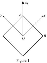
The length of the diagonal of a square is obtained by multiplying the side with
Write the expression for the angular velocity in the
Here,
Write the expression for the angular velocity in the
The unit vectors along the
Write the expression for the initial angular momentum about the mass center
Here,
Write the expression for the moment of inertia in the
Here, m is the mass and a is the side of the square plate.
Due to symmetry, moment of inertia in the
Write the expression for the angular momentum about
Substitute
Calculate the angular velocity at B
Here,
Substitute
The matrix multiplication for vector product is done.
The corner B does not rebound after impact. Therefore, the velocity of B after impact in the
Calculate the angular velocity about the mass center
Here,
Substitute
Substitute 0 for
Write the matrix multiplication for vector product is done.
Write the expression for the angular momentum about A as follows:
Here,
Calculate the angular momentum about G using the formula:
Substitute 0 for
Substitute
The matrix multiplication is done for vector product.
The initial velocity of mass center (
Calculate the initial momentum about A using the relation:
Here,
Substitute
Draw the forces acting on the plate as in Figure (2).
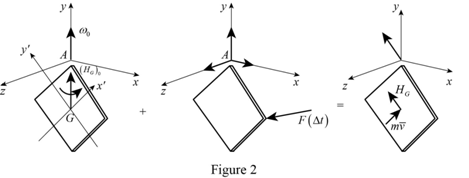
Write the expression for the moment about A as follows:
The matrix multiplication for vector product is done.
Substitute Equation (6) and Equation (7).
Equate
Equate
Equate
Calculate the velocity along the x, y and z axes
Substitute 0 for
Substitute
Calculate the kinetic energy of the system before impact
Substitute 0 for
Calculate the kinetic energy of the system after impact
Substitute
Calculate the loss in kinetic energy (U) using the formula:
Substitute
Thus, the kinetic energy (U) lost when plate hits the obstruction at B is
Want to see more full solutions like this?
Chapter 18 Solutions
VECTOR MECH...,STAT.+DYN.(LL)-W/ACCESS


- My ID# 016948724 last 2 ID# 24 Last 3 ID# 724 Please help to find the correct answer for this problem using my ID# first write le line of action and then help me to find the forces and the tension {fx= , fy= mz=arrow_forwardMy ID# 016948724 last 2 ID# 24 Last 3 ID# 724 Please help to find the correct answer for this problem using my ID# first write le line of action and then help me to find the forces {fx= , fy= mz=arrow_forwardmy ID is 016948724 Last 2 ID# 24 Last 3 ID# 724 please help me to solve this problem step by step show me how to solve first wirte the line actions and then find the forces {fx=, fy=, mz= and for the last step find the support reactions and find forcesarrow_forward
- Uppgift 1 (9p) 3 m 3 m 3 m 3 m H G F 3 m ↑ Dy D B AAY 30° 8 kN Ay Fackverket i figuren ovan är belastat med en punktlast. Bestäm normalkraften i stängerna BC, BG och FG.arrow_forwardThe cardiovascular countercurrent heat exchnager mechanism is to warm venous blood from 28 degrees C to 35 degrees C at a mass flow rate of 2 g/s. The artery inflow temp is 37 degrees C at a mass flow rate of 5 g/s. The average diameter of the vein is 5 cm and the overall heat transfer coefficient is 125 W/m^2*K. Determine the overall blood vessel length needed too warm the venous blood to 35 degrees C if the specific heat of both arterial and venous blood is constant and equal to 3475 J/kg*K.arrow_forwardThe forces Qy=12 kNQy=12kN and Qz=16 kNQz=16kN act on the profile at the shear center C. Calculate: a) Shear flow at point B (2 points)b) Shear stress at point D (3 points)arrow_forward
- Consider the feedback controlled blending system shown below, which is designed to keep theoutlet concentration constant despite potential variations in the stream 1 composition. The density of all streamsis 920 kg/m3. At the nominal steady state, the flow rates of streams 1 and 2 are 950 and 425 kg/min,respectively, the liquid level in the tank is 1.3 m, the incoming mass fractions are x1 = 0.27, x2 = 0.54. Noticethe overflow line, indicating that the liquid level remains constant (i.e. any change in total inlet flow ratetranslates immediately to the same change in the outlet flow rate). You may assume the stream 1 flowrate andthe stream 2 composition are both constant. Use minutes as the time unit throughout this problem. d) Derive the first order process and disturbance transfer functions;Gp= Kp/(tou*s+1) and Gd=Kd/(tou*s+1) and calculate and list the values and units of the parameters. e) Using the given information, write the general forms of Gm, GIP, and Gv below(in terms of…arrow_forwarda) Briefly explain what ratio control is. Give an example of a common chemical engineering situation in whichratio control would be useful and for that example state exactly how ratio control works (what would bemeasured, what is set, and how the controller logic works).b) Briefly explain what cascade control is. Give an example of a common chemical engineering situation inwhich cascade control would be useful and for that example state exactly how cascade control works (whatwould be measured, what is set, and how the controller logic works).arrow_forwardDetermine the reaction force acting on the beam AB, given F = 680 N. 5 4 4 m 3 3 A B 30° 3 m F (N)arrow_forward
- The frame in the figure is made of an HEA 300 profile (E = 210 GPa, material S355).a) Determine the support reactions at point A. (1p)b) Sketch the bending moment diagram caused by the loading. (1p)c) Using the principle of virtual work (unit load method), calculate the vertical displacement at point B using moment diagrams. Also take into account the compression of the column. (3p)arrow_forward9 kN/m 6 kN/m 3 m 6 m Bestäm, med hjälp av friläggning och jämviktsberäkningar, tvärkrafts- och momentdiagram för balken i figuren. Extrempunkter ska anges med både läge och värde.arrow_forwardB C 3.0 E F G 40 kN [m] 3.0 3.0 3.0 Fackverket belastas med en punktlast i G enligt figuren. Bestäm normalkraften i stängerna BC, BF och EF.arrow_forward
 Elements Of ElectromagneticsMechanical EngineeringISBN:9780190698614Author:Sadiku, Matthew N. O.Publisher:Oxford University Press
 Mechanics of Materials (10th Edition)Mechanical EngineeringISBN:9780134319650Author:Russell C. HibbelerPublisher:PEARSON
 Thermodynamics: An Engineering ApproachMechanical EngineeringISBN:9781259822674Author:Yunus A. Cengel Dr., Michael A. BolesPublisher:McGraw-Hill Education
 Control Systems EngineeringMechanical EngineeringISBN:9781118170519Author:Norman S. NisePublisher:WILEY
 Mechanics of Materials (MindTap Course List)Mechanical EngineeringISBN:9781337093347Author:Barry J. Goodno, James M. GerePublisher:Cengage Learning
 Engineering Mechanics: StaticsMechanical EngineeringISBN:9781118807330Author:James L. Meriam, L. G. Kraige, J. N. BoltonPublisher:WILEY