
Concept explainers
Find the maximum allowable load on a driven pile.
Answer to Problem 18.6P
The maximum allowable load on a driven pile is
Explanation of Solution
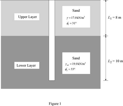
Given information:
The diameter of the driven pile D is 450 mm.
The length of the pile in the upper layer of the sand
The unit weight of the upper layer sand
The soil friction angle in the lower layer of sand
The length of the pile in the lower layer of the sand
The saturated unit weight of the lower layer sand
The soil friction angle in the lower layer of sand
The soil-pile friction-angle
The coefficient value K is
The factor of safety
Calculation:
Draw the cross section of the pile as in Figure 1.
Calculate the earth pressure coefficient
Here,
Substitute
Calculate the coefficient K for the upper layer using the formula.
Here,
Substitute 0.485 for
Calculate the earth pressure coefficient
Here,
Substitute
Calculate the coefficient K for the lower layer using the formula.
Here,
Substitute 0.455 for
Calculate the area of pile
Substitute 450 mm for D.
Calculate the perimeter p of the pile using the formula.
Substitute 450 mm for D.
Refer Figure (18.12), “Meyerhof’s bearing capacity factor,
Take the value of bearing capacity factor
Calculate the load-carrying capacity
Here,
Take the unit weight of water as
Substitute
Check the calculated value of load-carrying capacity of the pile point using Meyerhof’s equation.
Substitute
Use the lowest of the calculated value of load-carrying capacity of the pile point.
Calculate the soil-pile friction-angle
Substitute
Calculate the soil-pile friction-angle
Substitute
Calculate the critical depth of the pile
Substitute 450 mm for D.
Calculate the unit frictional resistance at the upper layer of sand.
Consider 0 ft from top of the pile.
Calculate the magnitude of unit frictional resistance
Substitute 0 m for z.
The frictional resistance (skin friction)
Consider the pile to the depth of 6.75 m (critical depth of the pile) from the top of pile tip.
Calculate the magnitude of unit frictional resistance
Substitute 6.75 m for z, 0.727 for
Calculate the magnitude of unit frictional resistance
Substitute 6.75 m for z, 0.727 for
Below the upper layer
Calculate the frictional resistance (skin friction)
Substitute 1.414 m for p, 6.75 m for
Calculate the frictional resistance (skin friction)
Substitute 1.414 m for p, 6.75 m for
Calculate the frictional resistance (skin friction)
Substitute 1.414 m for p, 10 m for
Calculate the ultimate load on the pile
Substitute 146.51 kN for
Calculate the allowable load on the pile
Substitute 1,125.27 kN for
Therefore, the load carrying capacity of the pile is
Want to see more full solutions like this?
Chapter 18 Solutions
Fundamentals of Geotechnical Engineering (MindTap Course List)


- Find forces in all members of the truss shown in Fig. Also find reactions at supports. 12 kN 20 kN ΙΟΧΟΙΟΙ 2 m 2 m 2 m 3 m C G E 4 m B Determine forces in members BC, GF and CG and nature of forces 9 m D 4 m C 4 m F 4 kN 6 kN 4 m 3 m B3 C E Assignment-2arrow_forwardPart 3: Problem-Solving. Solve the following problems. Show all calculations. 1. A retaining wall 5.80m high supports soil that has the following properties: Unit weight = 17.3 kN/m³ Angle of internal friction = 26 deg. Cohesion = 14.5 kPa a) Calculate the normal pressure acting at the back of the wall assuming no tensile crack occurs in the soil. b) Find the location of the tensile crack measured from the surface of horizontal backfill. c) Determine the active pressure acting on the wall in tensile crack occurs in the soil. 2. The soil material is supported by a retaining wall to a height of 6m. The unit weight of the soil is 16 kN/m³ and the angle of internal friction is 29 deg. Assume the soil is cohesionless. a) Determine the earth pressure on the wall. b) Find the total active pressure if surcharge of 14 kPa is applied on the surface of horizontal backfill. c) Locate the position of the total pressure from the bottom.arrow_forwardQuestion 3 (20 points): The traffic volume on a 2-lane highway is 1600 veh/hr in each direction Page 3 of 6 with a density of 20 veh/mi. A large dump truck enters the traffic stream from an adjacent construction site at 20 mph and carries on this way for 2 miles before turning off to the dump site. Because flow is so high in the opposite direction, no one can pass the truck. As a result, traffic back up behind the truck at four times the density (i.e., 4x20 = 80 veh/mi) at a volume of 1000 veh/hr. How many vehicles get caught in the traffic congestion before the truck exits the highway?arrow_forward
- How can construction project managers find a balance between speeding up schedules and the risks of making more mistakes and needing rework, especially when using methods like fast tracking?arrow_forwardHelp i keep getting the wrong answer. So I must be doing something wrong.arrow_forwardwhat is the workhours earned to date for concrete footings?arrow_forward
- What is the budgeted unit work hours, in work hours per unit for the concrete walls?arrow_forwardWhat are the total earned work hours at completion for the column forms?arrow_forward6000 units have been installed to date with 9,000 units to install. Labor costs are $23,300.00 to date. What is the unit cost for labor to date?arrow_forward
- The base rate for labor is $15/hr. The labor burden is 35% and 3% for small tools for the labor. There are 1000 units to install. Records indicate that trade workers can install 10 units per hour, per trade worker. The owners need 15% overhead and profit to pay bills, pay interest on loan and provide some profit to the partners. What is the minimum bid assuming no risk avoidance factor?arrow_forwardCan you show me how to obtain these answers thanks, will rate!arrow_forwardI have the answers for part a just need help with b mostly thanksarrow_forward
 Principles of Foundation Engineering (MindTap Cou...Civil EngineeringISBN:9781337705028Author:Braja M. Das, Nagaratnam SivakuganPublisher:Cengage Learning
 Fundamentals of Geotechnical Engineering (MindTap...Civil EngineeringISBN:9781305635180Author:Braja M. Das, Nagaratnam SivakuganPublisher:Cengage Learning
 Principles of Foundation Engineering (MindTap Cou...Civil EngineeringISBN:9781305081550Author:Braja M. DasPublisher:Cengage Learning
 Principles of Geotechnical Engineering (MindTap C...Civil EngineeringISBN:9781305970939Author:Braja M. Das, Khaled SobhanPublisher:Cengage Learning