Engineering Mechanics: Dynamics (14th Edition)
14th Edition
ISBN: 9780133915389
Author: Russell C. Hibbeler
Publisher: PEARSON
expand_more
expand_more
format_list_bulleted
Concept explainers
Textbook Question
Chapter 17.3, Problem 1PP
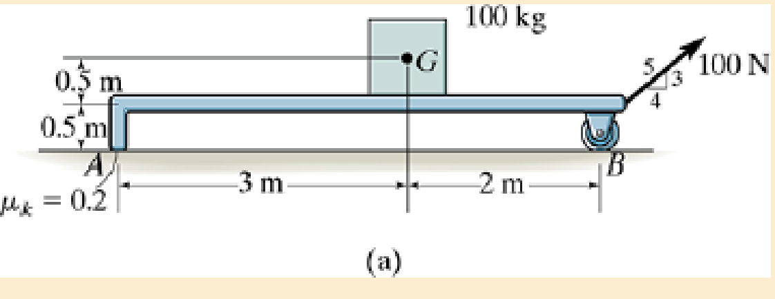
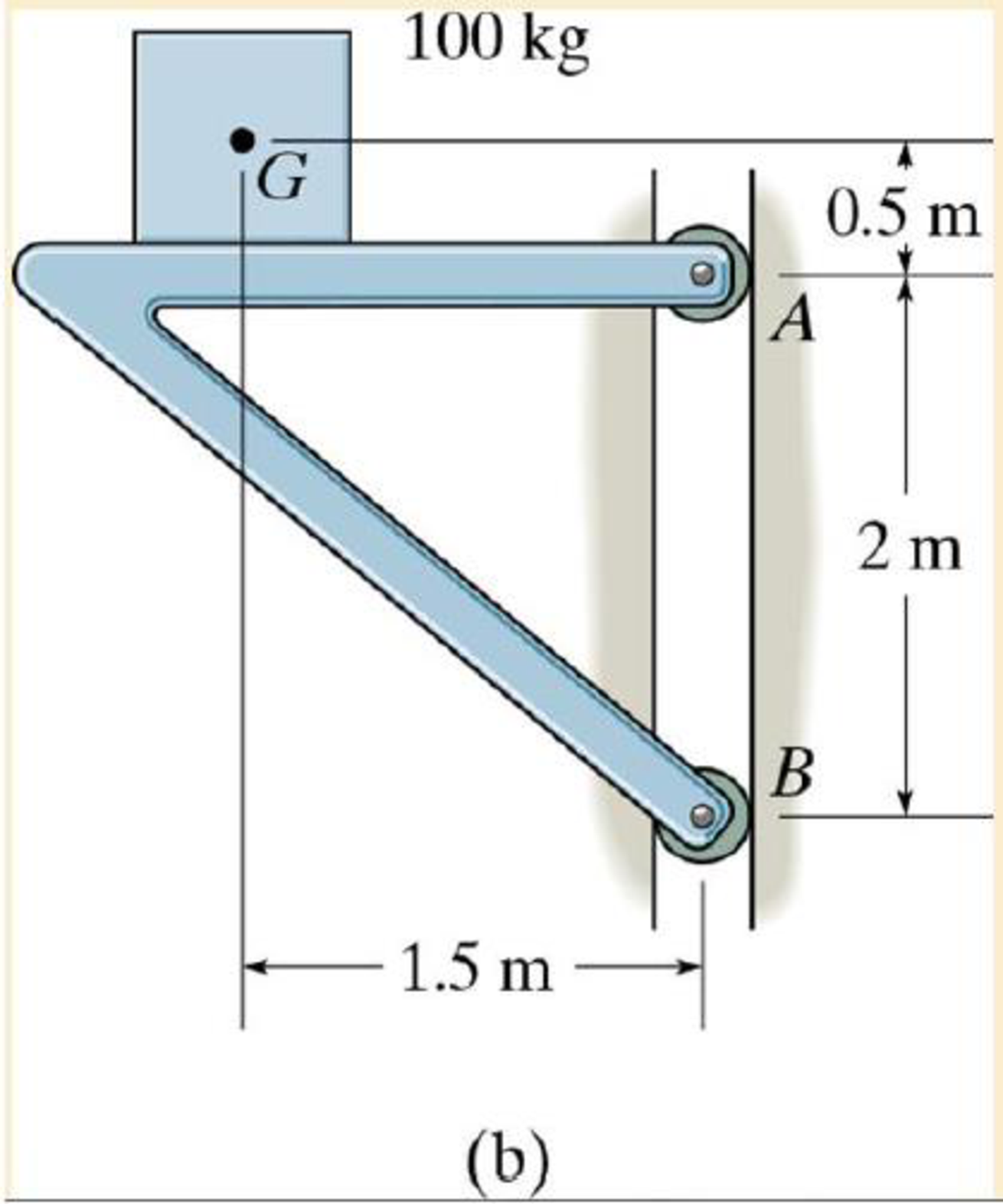
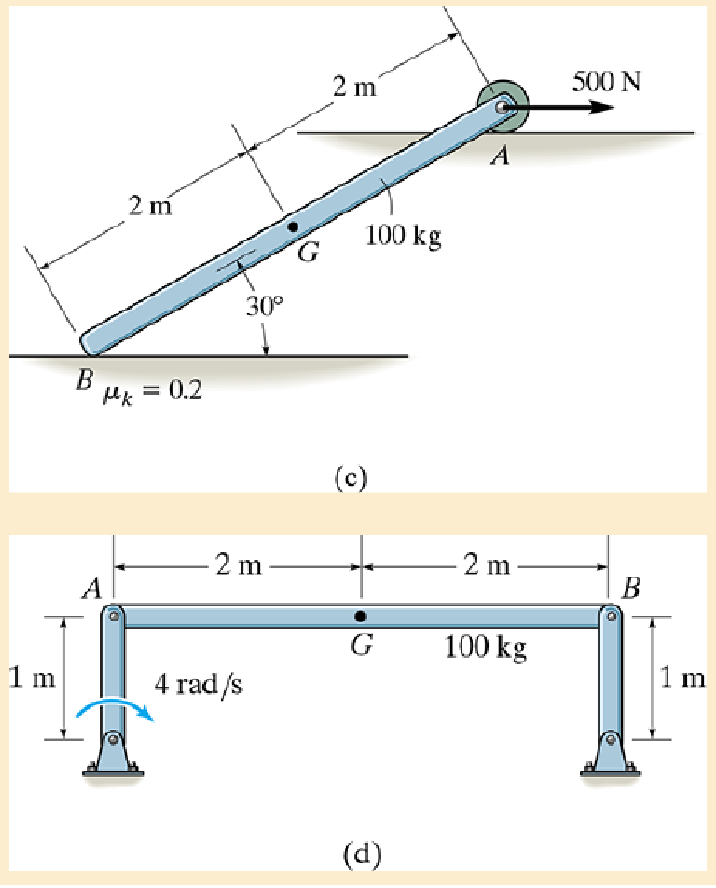
Draw the free-body and kinetic diagrams of the object AB.


Expert Solution & Answer
Want to see the full answer?
Check out a sample textbook solution
Students have asked these similar questions
If you have a spring mass damper system, given by m*x_double_dot + c*x_dot + kx = 0 where m, c, k (all positive scalars) are the mass, damper coefficient, and spring coefficient, respectively. x ∈ R represents the displacement of the mass.
Using linear stability analysis, show that the system is asymptotically stable.
Hint: stability of a linear system z_dot = Az is characterized by the eigenvalues of A.
What would the electropneumatic diagram of a circuit with the sequence a+b+c+(a-b-c-) look like?
### What would the electropneumatic diagram of a circuit with the sequence a+b+c+(a-b-c-) look like, with a counter, in the fluidsim?
Chapter 17 Solutions
Engineering Mechanics: Dynamics (14th Edition)
Ch. 17.1 - The rod's density end cross-sectional area. A are...Ch. 17.1 - Determine the mass of the cylinder end its moment...Ch. 17.1 - The nag has a mass m.Ch. 17.1 - Determine the radius of gyration kx. The density...Ch. 17.1 - The specific weight of the material is = 380...Ch. 17.1 - Determine the moment of inertia Iz and express the...Ch. 17.1 - Determine the moment of inertia Ix and express the...Ch. 17.1 - Defending the moment of inertia Iy and express the...Ch. 17.1 - Express the result in terms of the mass m of the...Ch. 17.1 - Determine me radius of gyration of the pendulum...
Ch. 17.1 - Determine the mass moment of inertia of the...Ch. 17.1 - Determine the moment of inertia of the solid steel...Ch. 17.1 - Determine the wheels moment of inertia about an...Ch. 17.1 - If the large ring, small ring and each of the...Ch. 17.1 - The thin plate has a hole in its center its...Ch. 17.1 - The material has a mass per unit area of 20 kg/m2.Ch. 17.1 - The block has a mass of 3 kg and the semicylinder...Ch. 17.1 - The block has a mass of 3 kg and the semicylinder...Ch. 17.1 - The material has a specific weight = 90 lb/ft3.Ch. 17.1 - Prob. 20PCh. 17.1 - Determine the location y of the center of mass G...Ch. 17.1 - The material is steel having a density of = 7.85...Ch. 17.1 - The material is steel having a density of = 7.85...Ch. 17.3 - Draw the free-body and kinetic diagrams of the...Ch. 17.3 - Draw the free-body and kinetic diagrams of the...Ch. 17.3 - Determine the acceleration of the can and the...Ch. 17.3 - If the 80-kg cabinet is allowed to roll down the...Ch. 17.3 - Determine the maximum acceleration of the frame...Ch. 17.3 - Also what is the corresponding normal reaction on...Ch. 17.3 - Determine the tension developed in the rods and...Ch. 17.3 - If it is subjected to a couple moment M = 450 N ...Ch. 17.3 - Determine how far the door moves in 25, starting...Ch. 17.3 - Determine the constant force F that must be...Ch. 17.3 - Initially at take-off the engines provide a thrust...Ch. 17.3 - If it starts from rest it causes the rear wheels...Ch. 17.3 - If the winch at B draws in the cable with an...Ch. 17.3 - Determine the greatest acceleration of the...Ch. 17.3 - Determine the internal axial, shear, and...Ch. 17.3 - If the coefficient of kinetic friction between the...Ch. 17.3 - Determine the reactions at both the wheels at A...Ch. 17.3 - Also, what is the acceleration of the cart? The...Ch. 17.3 - If it is subjected to a horizontal force of P =...Ch. 17.3 - Determine its initial acceleration if a man pushes...Ch. 17.3 - Determine the initial acceleration of a desk when...Ch. 17.3 - Determine the maximum force P that can be applied...Ch. 17.3 - Determine the maximum force P that can be applied...Ch. 17.3 - If it is released from rest, determine the...Ch. 17.3 - It is carried on a truck as shown. Determine the...Ch. 17.3 - It is carried on a truck as shown. If the truck...Ch. 17.3 - Determine the smallest acceleration that will...Ch. 17.3 - The coefficients of static and kinetic friction...Ch. 17.3 - If the collar is given a constant acceleration of...Ch. 17.3 - If it is supported by the cable AB and hinge at C,...Ch. 17.3 - If it is supported by the cable AB and hinge at C,...Ch. 17.3 - If the acceleration is a = 20 ft/s2, determine the...Ch. 17.3 - If h = 3 ft, determine the snowmobiles maximum...Ch. 17.3 - If the carts mass is 30 kg and it is subjected to...Ch. 17.3 - The uniform rod BC has a mass of 15 kg.Ch. 17.3 - If the acceleration of the truck is at = 0.5 m/s2,...Ch. 17.3 - If the angle = 30, determine the acceleration of...Ch. 17.3 - Determine the largest initial angular acceleration...Ch. 17.3 - Determine the initial friction and normal force of...Ch. 17.3 - Determine the largest initial angular acceleration...Ch. 17.3 - Determine the normal force NE, shear force VE, and...Ch. 17.4 - If the wheel starts from rest determine its...Ch. 17.4 - Determine the angular velocity of the disk when t...Ch. 17.4 - Determine the tangential and normal components of...Ch. 17.4 - Determine the tangential and normal components or...Ch. 17.4 - Determine the horizontal and vertical components...Ch. 17.4 - If the rod has a counterclockwise angular velocity...Ch. 17.4 - If the wheel is subjected to a moment M = (5t) N ...Ch. 17.4 - Determine its initial angular acceleration and the...Ch. 17.4 - If it is released from rest when = 0. determine...Ch. 17.4 - If it is released from rest in the position shown,...Ch. 17.4 - The reel rests on rollers at A and B and has a...Ch. 17.4 - The spring has a stiffness k = 5 lb ft/rad, so...Ch. 17.4 - The spring has a stiffness k = 5 lb ft/rad, so...Ch. 17.4 - If a force of F=(142)N, where is in radians, is...Ch. 17.4 - If no slipping occurs between them determine the...Ch. 17.4 - Show that IG may be eliminated by moving the...Ch. 17.4 - Treat the beam as a uniform slender rod.Ch. 17.4 - It consists of a 100-kg steel plate AC and a...Ch. 17.4 - It is pin supported at both ends by two brackets...Ch. 17.4 - It is pin supported at both ends by two brackets...Ch. 17.4 - Determine its angular velocity when t = 2 s...Ch. 17.4 - If it is placed on the ground for which the...Ch. 17.4 - Compute the time needed to unravel 5 m of cable...Ch. 17.4 - If the rotor always maintains a constant clockwise...Ch. 17.4 - It is originally spinning at = 40 rad/s. If it is...Ch. 17.4 - It is pin supported at both ends by two brackets...Ch. 17.4 - Disk E has a weight of 60 lb and is initially at...Ch. 17.4 - If the cylinders are released from rest, determine...Ch. 17.4 - If the pulley can be treated as a disk of mass 3...Ch. 17.4 - If the pulley can be treated as a disk of mass M,...Ch. 17.4 - Assume that the board is uniform and rigid, and...Ch. 17.4 - At the instant the rolor is horizontal it has an...Ch. 17.4 - Determine the initial tending moment at the fixed...Ch. 17.4 - Movement is controlled by the electromagnet E,...Ch. 17.4 - If it is rotating in the vertical plane at a...Ch. 17.4 - Determine the angular acceleration of the rod and...Ch. 17.4 - Determine the horizontal and vertical components...Ch. 17.4 - Determine the horizontal and vertical components...Ch. 17.5 - If the powder burns at a constant rate of 20 g/s...Ch. 17.5 - Determine the acceleration of the bars mass center...Ch. 17.5 - Determine the acceleration of its mass center and...Ch. 17.5 - When the wheel is subjected to the couple moment,...Ch. 17.5 - Determine the angular acceleration of the sphere...Ch. 17.5 - If the couple moment is applied to the spool and...Ch. 17.5 - If the rod is released from rest at = 0,...Ch. 17.5 - rolls without slipping, show that when moments are...Ch. 17.5 - If it is initially at rest and is subjected to a...Ch. 17.5 - The uniform 150-lb beam is initially at rest when...Ch. 17.5 - If the coefficients of static and kinetic friction...Ch. 17.5 - If the coefficients of static and kinetic friction...Ch. 17.5 - If the coefficients of static and kinetic friction...Ch. 17.5 - Solve Prob.17-96 if the cord and force P = 50 N...Ch. 17.5 - If the coefficients of static and kinetic friction...Ch. 17.5 - If a horizontal force of F = 80 N is applied to...Ch. 17.5 - If slipping does not occur, determine the rings...Ch. 17.5 - Neglect the thickness of the ring.Ch. 17.5 - Using a collar of negligible mass, its end A is...Ch. 17.5 - If the pin is connected to a track which is giver...Ch. 17.5 - Assume the roller to be a uniform cylinder and...Ch. 17.5 - Also, find the angular acceleration of the roller....Ch. 17.5 - Determine the bars initial angular acceleration...Ch. 17.5 - Solve Prob.17-106 if the roller is removed and the...Ch. 17.5 - If the coefficient of static friction at A is s, =...Ch. 17.5 - If the truck has an acceleration of 3 m/s2...Ch. 17.5 - A cord is wrapped around the periphery of the disk...Ch. 17.5 - If the coefficient of static friction at A is s =...Ch. 17.5 - At this instant the center of gravity of the...Ch. 17.5 - Determine the initial angular acceleration of the...Ch. 17.5 - Determine the time before it starts to roll...Ch. 17.5 - If they are released from rest determine the...Ch. 17.5 - Determine the normal force which the path exerts...Ch. 17.5 - If it is originally at rest while being supported...Ch. 17.5 - If the pin support at A suddenly fails, determine...Ch. 17.5 - Determine its angular acceleration.Ch. 17.5 - If the coefficient of kinetic friction between the...Ch. 17.5 - Determine the normal reactions at each of the...Ch. 17.5 - Determine the internal axial force Ex, shear force...Ch. 17.5 - Determine the maximum acceleration it can have if...Ch. 17.5 - The roil rest against a wall for which the...Ch. 17.5 - Determine the magnitude of force F and the initial...Ch. 17.5 - Compute the reaction at the pin O just after the...Ch. 17.5 - if the coefficient of kinetic friction at the...Ch. 17.5 - The coefficient of kinetic friction is A = 0.3.
Knowledge Booster
Learn more about
Need a deep-dive on the concept behind this application? Look no further. Learn more about this topic, mechanical-engineering and related others by exploring similar questions and additional content below.Similar questions
- You are asked to design a unit to condense ammonia. The required condensation rate is 0.09kg/s. Saturated ammonia at 30 o C is passed over a vertical plate (10 cm high and 25 cm wide).The properties of ammonia at the saturation temperature of 30°C are hfg = 1144 ́10^3 J/kg andrv = 9.055 kg/m 3 . Use the properties of liquid ammonia at the film temperature of 20°C (Ts =10 o C):Pr = 1.463 rho_l= 610.2 kf/m^3 liquid viscosity= 1.519*10^-4 kg/ ms kinematic viscosity= 2.489*10^-7 m^2/s Cpl= 4745 J/kg C kl=0.4927 W/m CCalculate the surface temperature required to achieve the desired condensation rate of 0.09 kg/s( should be 688 degrees C) a) Show that if you use a bigger vertical plate (2.5 m-wide and 0.8 m-height), the requiredsurface temperature would be now 20 o C. You may use all the properties given as an initialguess. No need to iterate to correct for Tf. b) What if you still want to use small plates because of the space constrains? One way to getaround this problem is to use small…arrow_forwardA differential element on the bracket is subjected to plane strain that has the following components:, Ɛx = 300 × 10-6, Ɛy = 150 × 10-6, Ɛxy = -750 x 10-6. Use the strain-transformation equations and determine the normal strain Ɛx in the X/ direction on an element oriented at an angle of 0 = 40°. Note, a positive angle, 0, is counter clockwise. x Enter your answer in micro strain to a precision of two decimal places. eg. if your answer is 300.15X10⁶, please enter 300.15.arrow_forwardIf the 50 mm diameter shaft is made from brittle material having an ultimate strength of σult=595 MPa for both tension and compression, determine the factor of safety of the shaft against rupture. The applied force, F, is 140 kN. The applied torque T, is 5.0 kN⚫m. Enter your answer to a precision of two decimal places. T Farrow_forwardЗіс 1 mH 10 Ω m 16 cos 2.5 × 10⁴ A Lic 592 10 Ω 1 μFarrow_forwardHomework#5arrow_forwardHomework#5arrow_forwardOxygen (molar mass 32 kg/kmol) expands reversibly in a cylinder behind a piston at a constant pressure of 3 bar. The volume initially is 0.01 m3 and finally is 0.03 m3; the initial temperature is 17°C. Calculate the work input and the heat supplied during the expansion. Assume oxygen to be an ideal gas and take cp = 0.917 kJ/kg K. For 1 bonus mark explain why (using your understanding of thermodynamics) that oxygen is used in this context rather than water vapour.arrow_forwardHydrodynamic Lubrication Theory Q1: Convert this equations into Python by 1- ah ap a h³ ap 1..ah = ax 12μ ax ay 12μ ay 2 ax Where P=P(x, y) is the oil film pressure. 2- 3μU (L² ε sin P= C²R (1+ cos 0)³ Q2: prove that |h(0) = C(1+ cos 0) ?arrow_forward### To make a conclusion for a report of an experiment on rockets, in which the openrocket software was used for the construction and modeling of two rockets: one one-stage and one two-stage. First rocket (single-stage) reached a maximum vertical speed of 200 m/s and a maximum height of 1000 m The second rocket (two-stage) reached a maximum vertical speed of 250 m/s and a maximum height of 1800 m To make a simplified conclusion, taking into account the efficiency of the software in the study of rocketsarrow_forwardWhat is the difference between saturated liquid and compressed liquid? What is the difference between the critical point and the triple pointarrow_forwardarrow_back_iosSEE MORE QUESTIONSarrow_forward_ios
Recommended textbooks for you
 International Edition---engineering Mechanics: St...Mechanical EngineeringISBN:9781305501607Author:Andrew Pytel And Jaan KiusalaasPublisher:CENGAGE L

International Edition---engineering Mechanics: St...
Mechanical Engineering
ISBN:9781305501607
Author:Andrew Pytel And Jaan Kiusalaas
Publisher:CENGAGE L
Dynamics - Lesson 1: Introduction and Constant Acceleration Equations; Author: Jeff Hanson;https://www.youtube.com/watch?v=7aMiZ3b0Ieg;License: Standard YouTube License, CC-BY