
EBK FUNDAMENTALS OF ELECTRIC CIRCUITS
6th Edition
ISBN: 8220102801448
Author: Alexander
Publisher: YUZU
expand_more
expand_more
format_list_bulleted
Concept explainers
Videos
Textbook Question
Chapter 17, Problem 7P
Determine the Fourier series of the periodic function in Fig. 17.50.
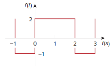
Figure 17.50
Expert Solution & Answer
Want to see the full answer?
Check out a sample textbook solution
Students have asked these similar questions
Find Va and Vb using mesh analysis
Find Va and Vb using Mesh analysis
Find Va and Vb using nodal analysis
Chapter 17 Solutions
EBK FUNDAMENTALS OF ELECTRIC CIRCUITS
Ch. 17.2 - Find the Fourier series of the square wave in Fig....Ch. 17.2 - Determine the Fourier series of the sawtooth...Ch. 17.3 - Prob. 3PPCh. 17.3 - Find the Fourier series expansion of the function...Ch. 17.3 - Prob. 5PPCh. 17.4 - Prob. 6PPCh. 17.4 - If the input voltage in the circuit of Fig. 17.24...Ch. 17.5 - The voltage and current at the terminals of a...Ch. 17.5 - Find the rms value of the periodic current i(t) =...Ch. 17.6 - Obtain the complex Fourier series of the function...
Ch. 17.6 - Obtain the complex Fourier series expansion of...Ch. 17.7 - Prob. 12PPCh. 17.8 - Rework Example 17.14 if the low-pass filter is...Ch. 17 - Which of the following cannot be a Fourier series?...Ch. 17 - If ft=t,0t,ft+n=ft, the value of 0 is (a) 1 (b) 2...Ch. 17 - Which of the following are even functions? (a) t +...Ch. 17 - Prob. 4RQCh. 17 - Prob. 5RQCh. 17 - If f(t) = 10 + 8 cos t + 4 cos 3t + 2 cos 5t + ,...Ch. 17 - Prob. 7RQCh. 17 - The plot of |cn| versus n0 is called: (a) complex...Ch. 17 - Prob. 9RQCh. 17 - Prob. 10RQCh. 17 - Evaluate each of the following functions and see...Ch. 17 - Using MATLAB, synthesize the periodic waveform for...Ch. 17 - Given that Fourier coefficients a0, an, and bn of...Ch. 17 - Find the Fourier series expansion of the backward...Ch. 17 - Prob. 5PCh. 17 - Find the trigonometric Fourier series for f t =...Ch. 17 - Determine the Fourier series of the periodic...Ch. 17 - Using Fig. 17.51, design a problem to help other...Ch. 17 - Determine the Fourier coefficients an and bn of...Ch. 17 - Find the exponential Fourier series for the...Ch. 17 - Obtain the exponential Fourier series for the...Ch. 17 - Prob. 12PCh. 17 - Prob. 13PCh. 17 - Find the quadrature (cosine and sine) form of the...Ch. 17 - Express the Fourier series...Ch. 17 - The waveform in Fig. 17.55(a) has the following...Ch. 17 - Prob. 17PCh. 17 - Prob. 18PCh. 17 - Obtain the Fourier series for the periodic...Ch. 17 - Prob. 20PCh. 17 - Prob. 21PCh. 17 - Calculate the Fourier coefficients for the...Ch. 17 - Using Fig. 17.61, design a problem to help other...Ch. 17 - Prob. 24PCh. 17 - Determine the Fourier series representation of the...Ch. 17 - Find the Fourier series representation of the...Ch. 17 - For the waveform shown in Fig. 17.65 below, (a)...Ch. 17 - Obtain the trigonometric Fourier series for the...Ch. 17 - Prob. 29PCh. 17 - Prob. 30PCh. 17 - Prob. 31PCh. 17 - Prob. 32PCh. 17 - Prob. 33PCh. 17 - Prob. 34PCh. 17 - Prob. 35PCh. 17 - Prob. 36PCh. 17 - If the periodic current waveform in Fig. 17.73(a)...Ch. 17 - Prob. 38PCh. 17 - Prob. 39PCh. 17 - The full-wave rectified sinusoidal voltage in Fig....Ch. 17 - Prob. 42PCh. 17 - The voltage across the terminals of a circuit is...Ch. 17 - Prob. 44PCh. 17 - A series RLC circuit has R = 10 , L = 2 mH, and C...Ch. 17 - Prob. 46PCh. 17 - Prob. 47PCh. 17 - Prob. 48PCh. 17 - Prob. 49PCh. 17 - Prob. 50PCh. 17 - Prob. 51PCh. 17 - Prob. 52PCh. 17 - Prob. 53PCh. 17 - Find the exponential Fourier series for the...Ch. 17 - Obtain the exponential Fourier series expansion of...Ch. 17 - The Fourier series trigonometric representation of...Ch. 17 - Prob. 57PCh. 17 - Find the exponential Fourier series of a function...Ch. 17 - Prob. 59PCh. 17 - Obtain the complex Fourier coefficients of the...Ch. 17 - The spectra of the Fourier series of a function...Ch. 17 - Prob. 62PCh. 17 - Plot the amplitude spectrum for the signal f2(t)...Ch. 17 - Prob. 64PCh. 17 - Prob. 65PCh. 17 - Prob. 66PCh. 17 - Prob. 67PCh. 17 - Prob. 68PCh. 17 - Prob. 69PCh. 17 - Design a problem to help other students better...Ch. 17 - Prob. 71PCh. 17 - Prob. 72PCh. 17 - Prob. 73PCh. 17 - Prob. 74PCh. 17 - Prob. 75PCh. 17 - Prob. 76PCh. 17 - Prob. 77CPCh. 17 - Prob. 78CPCh. 17 - Consider the full-wave rectified sinusoidal...Ch. 17 - Prob. 82CP
Knowledge Booster


Learn more about
Need a deep-dive on the concept behind this application? Look no further. Learn more about this topic, electrical-engineering and related others by exploring similar questions and additional content below.Similar questions
- 2. Using the approximate method, hand sketch the Bode plot for the following transfer functions. a) H(s) = 10 b) H(s) (s+1) c) H(s): = 1 = +1 100 1000 (s+1) 10(s+1) d) H(s) = (s+100) (180+1)arrow_forwardQ4: Write VHDL code to implement the finite-state machine described by the state Diagram in Fig. 1. Fig. 1arrow_forward1. Consider the following feedback system. Bode plot of G(s) is shown below. Phase (deg) Magnitude (dB) -50 -100 -150 -200 0 -90 -180 -270 101 System: sys Frequency (rad/s): 0.117 Magnitude (dB): -74 10° K G(s) Bode Diagram System: sys Frequency (rad/s): 36.8 Magnitude (dB): -99.7 System: sys Frequency (rad/s): 20 Magnitude (dB): -89.9 System: sys Frequency (rad/s): 20 Phase (deg): -143 System: sys Frequency (rad/s): 36.8 Phase (deg): -180 101 Frequency (rad/s) a) Determine the range of K for which the closed-loop system is stable. 102 10³ b) If we want the gain margin to be exactly 50 dB, what is value for K we should choose? c) If we want the phase margin to be exactly 37°, what is value of K we should choose? What will be the corresponding rise time (T) for step-input? d) If we want steady-state error of step input to be 0.6, what is value of K we should choose?arrow_forward
- : Write VHDL code to implement the finite-state machine/described by the state Diagram in Fig. 4. X=1 X=0 solo X=1 X=0 $1/1 X=0 X=1 X=1 52/2 $3/3 X=1 Fig. 4 X=1 X=1 56/6 $5/5 X=1 54/4 X=0 X-O X=O 5=0 57/7arrow_forwardQuestions: Q1: Verify that the average power generated equals the average power absorbed using the simulated values in Table 7-2. Q2: Verify that the reactive power generated equals the reactive power absorbed using the simulated values in Table 7-2. Q3: Why it is important to correct the power factor of a load? Q4: Find the ideal value of the capacitor theoretically that will result in unity power factor. Vs pp (V) VRIPP (V) VRLC PP (V) AT (μs) T (us) 8° pf Simulated 14 8.523 7.84 84.850 1000 29.88 0.866 Measured 14 8.523 7.854 82.94 1000 29.85 0.86733 Table 7-2 Power Calculations Pvs (mW) Qvs (mVAR) PRI (MW) Pay (mW) Qt (mVAR) Qc (mYAR) Simulated -12.93 -7.428 9.081 3.855 12.27 -4.84 Calculated -12.936 -7.434 9.083 3.856 12.32 -4.85 Part II: Power Factor Correction Table 7-3 Power Factor Correction AT (us) 0° pf Simulated 0 0 1 Measured 0 0 1arrow_forwardQuestions: Q1: Verify that the average power generated equals the average power absorbed using the simulated values in Table 7-2. Q2: Verify that the reactive power generated equals the reactive power absorbed using the simulated values in Table 7-2. Q3: Why it is important to correct the power factor of a load? Q4: Find the ideal value of the capacitor theoretically that will result in unity power factor. Vs pp (V) VRIPP (V) VRLC PP (V) AT (μs) T (us) 8° pf Simulated 14 8.523 7.84 84.850 1000 29.88 0.866 Measured 14 8.523 7.854 82.94 1000 29.85 0.86733 Table 7-2 Power Calculations Pvs (mW) Qvs (mVAR) PRI (MW) Pay (mW) Qt (mVAR) Qc (mYAR) Simulated -12.93 -7.428 9.081 3.855 12.27 -4.84 Calculated -12.936 -7.434 9.083 3.856 12.32 -4.85 Part II: Power Factor Correction Table 7-3 Power Factor Correction AT (us) 0° pf Simulated 0 0 1 Measured 0 0 1arrow_forward
- electric plants. Prepare the load schedulearrow_forwardelectric plants Draw the column diagram. Calculate the voltage drop. by hand writingarrow_forwardelectric plants. Draw the lighting, socket, telephone, TV, and doorbell installations on the given single-story project with an architectural plan by hand writingarrow_forward
- A circularly polarized wave, traveling in the +z-direction, is received by an elliptically polarized antenna whose reception characteristics near the main lobe are given approx- imately by E„ = [2â, + jâ‚]ƒ(r. 8, 4) Find the polarization loss factor PLF (dimensionless and in dB) when the incident wave is (a) right-hand (CW) An elliptically polarized wave traveling in the negative z-direction is received by a circularly polarized antenna. The vector describing the polarization of the incident wave is given by Ei= 2ax + jay.Find the polarization loss factor PLF (dimensionless and in dB) when the wave that would be transmitted by the antenna is (a) right-hand CParrow_forwardjX(1)=j0.2p.u. jXa(2)=j0.15p.u. jxa(0)=0.15 p.u. V₁=1/0°p.u. V₂=1/0° p.u. 1 jXr(1) = j0.15 p.11. jXT(2) = j0.15 p.u. jXr(0) = j0.15 p.u. V3=1/0° p.u. А V4=1/0° p.u. 2 jX1(1)=j0.12 p.u. 3 jX2(1)=j0.15 p.u. 4 jX1(2)=0.12 p.11. JX1(0)=0.3 p.u. jX/2(2)=j0.15 p.11. X2(0)=/0.25 p.1. Figure 1. Circuit for Q3 b).arrow_forwardcan you show me full workings for this problem. the solution is - v0 = 10i2 = 2.941 volts, i0 = i1 – i2 = (5/3)i2 = 490.2mA.arrow_forward
arrow_back_ios
SEE MORE QUESTIONS
arrow_forward_ios
Recommended textbooks for you
 Introductory Circuit Analysis (13th Edition)Electrical EngineeringISBN:9780133923605Author:Robert L. BoylestadPublisher:PEARSON
 Delmar's Standard Textbook Of ElectricityElectrical EngineeringISBN:9781337900348Author:Stephen L. HermanPublisher:Cengage Learning
 Programmable Logic ControllersElectrical EngineeringISBN:9780073373843Author:Frank D. PetruzellaPublisher:McGraw-Hill Education
 Fundamentals of Electric CircuitsElectrical EngineeringISBN:9780078028229Author:Charles K Alexander, Matthew SadikuPublisher:McGraw-Hill Education
 Electric Circuits. (11th Edition)Electrical EngineeringISBN:9780134746968Author:James W. Nilsson, Susan RiedelPublisher:PEARSON
 Engineering ElectromagneticsElectrical EngineeringISBN:9780078028151Author:Hayt, William H. (william Hart), Jr, BUCK, John A.Publisher:Mcgraw-hill Education,
Introductory Circuit Analysis (13th Edition)
Electrical Engineering
ISBN:9780133923605
Author:Robert L. Boylestad
Publisher:PEARSON
Delmar's Standard Textbook Of Electricity
Electrical Engineering
ISBN:9781337900348
Author:Stephen L. Herman
Publisher:Cengage Learning
Programmable Logic Controllers
Electrical Engineering
ISBN:9780073373843
Author:Frank D. Petruzella
Publisher:McGraw-Hill Education
Fundamentals of Electric Circuits
Electrical Engineering
ISBN:9780078028229
Author:Charles K Alexander, Matthew Sadiku
Publisher:McGraw-Hill Education
Electric Circuits. (11th Edition)
Electrical Engineering
ISBN:9780134746968
Author:James W. Nilsson, Susan Riedel
Publisher:PEARSON
Engineering Electromagnetics
Electrical Engineering
ISBN:9780078028151
Author:Hayt, William H. (william Hart), Jr, BUCK, John A.
Publisher:Mcgraw-hill Education,
Intro to FOURIER SERIES: The Big Idea; Author: Dr. Trefor Bazett;https://www.youtube.com/watch?v=wmCIrpLBFds;License: Standard Youtube License