
Concept explainers
Videos
Obtain the exponential Fourier series for the signal in Fig. 17.54.
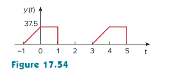
Find the exponential Fourier series for the signal in Figure 17.54.
Answer to Problem 11P
The exponential Fourier series
Explanation of Solution
Given data:
Refer to Figure 17.54 in the textbook.
Formula used:
Write the expression to calculate the fundamental angular frequency.
Here,
Write the general expression to calculate exponential Fourier series of
Here,
Write the expression to calculate exponential Fourier series coefficients.
Calculation:
The given waveform is drawn as Figure 1.
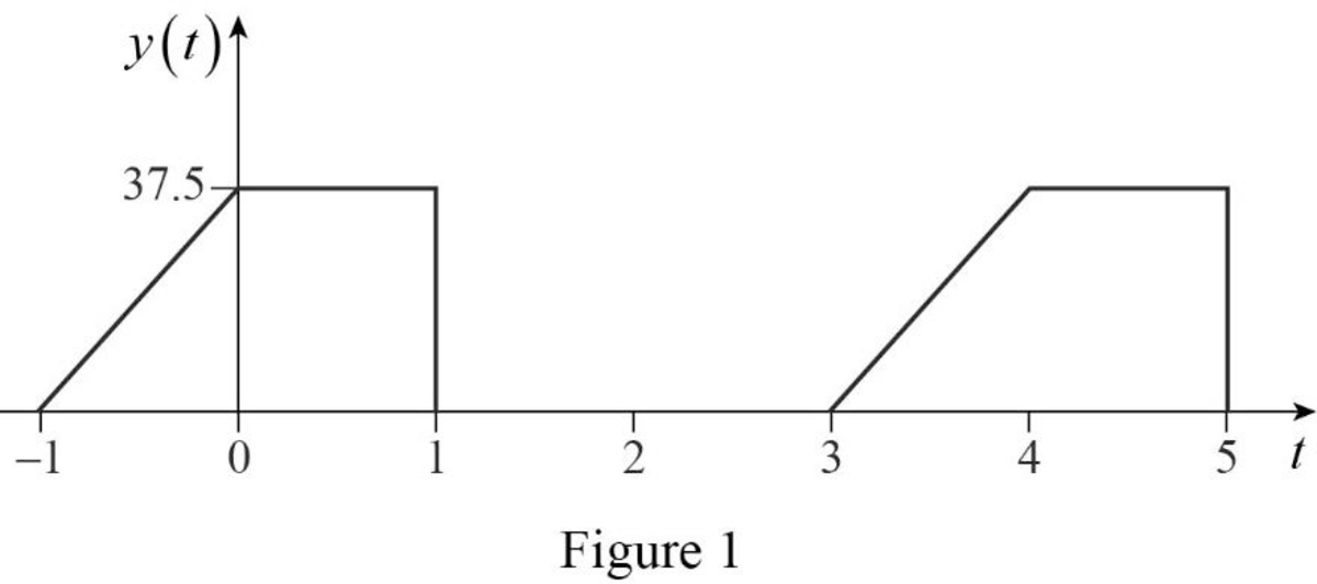
Refer to Figure 1. The Fourier series function is defined as,
The time period of the function in Figure 1 is,
Substitute
Substitute
Simplify the above equation to find
Simplify the above equation to find
Assume the following to reduce the equation (4).
Substitute the equations (5) in equation (4) to find
Consider the following integration formula.
Compare the equations (5) and (7) to simplify the equation (5).
Using the equation (7), the equation (5) can be reduced as,
Simplify the above equation to find
Simplify the above equation to find
Substitute
Substitute
Conclusion:
Thus, the exponential Fourier series
Want to see more full solutions like this?
Chapter 17 Solutions
EBK FUNDAMENTALS OF ELECTRIC CIRCUITS


- Please solve it by explaining the steps. I am trying to prepare for my exam tomorrow, so any tips and tricks to solve similar problems are highly appreciated. Plus, this is a past exam I am using to prepare.arrow_forwardPlease solve it by explaining the steps. I am trying to prepare for my exam tomorrow, so any tips and tricks to solve similar problems are highly appreciated. Plus, this is a past exam I am using to prepare.arrow_forwardPlease solve it by explaining the steps. I am trying to prepare for my exam tomorrow, so any tips and tricks to solve similar problems are highly appreciated. Plus, this is a past exam I am using to prepare.arrow_forward
- Please solve it by explaining the steps. I am trying to prepare for my exam tomorrow, so any tips and tricks to solve similar problems are highly appreciated. Plus, this is a past exam I am using to prepare.arrow_forwardPlease solve it by explaining the steps. I am trying to prepare for my exam tomorrow, so any tips and tricks to solve similar problems are highly appreciated. Plus, this is a past exam I am using to prepare.arrow_forwardPlease solve it by explaining the steps. I am trying to prepare for my exam tomorrow, so any tips and tricks to solve similar problems are highly appreciated. Plus, this is a past exam I am using to prepare.arrow_forward
- It is a past exam for practice, please explain what you do so I can be prepared for exam tomorrowarrow_forwardPlease solve it by explaining the steps. I am trying to prepare for my exam tomorrow, so any tips and tricks to solve similar problems are highly appreciated. Plus, this is a past exam I am using to prepare.arrow_forwardPlease solve it by explaining the steps. I am trying to prepare for my exam tomorrow, so any tips and tricks to solve similar problems are highly appreciated. Plus, this is a past exam I am using to prepare.arrow_forward
- Please solve it by explaining the steps. I am trying to prepare for my exam tomorrow, so any tips and tricks to solve similar problems are highly appreciated. Plus, this is a past exam I am using to prepare.arrow_forwardIf C is the circle |z|=4 evaluate ff(z)dz for each of the following functions using residue. Z (a)f(z) = z²-1 Z+1 1 (b)f(z) = = (c)f(z) = z²(z+2) z(z-2)³ z² 1 1 (d) f(z) = = (e) f(z) = (f) f(z) = (z²+3z+2)² z²+z+1 z(z²+6z+4)arrow_forward5. Answer the following questions. Take help from ChatGPT to answer these questions (if you need). Write the answers briefly using your own words with no more than two sentences, and check whether ChatGPT is giving you the appropriate answers in the context of our class. a) What is the Bode plot? What kind of input do we consider for the frequency-response- based method? b) What is the advantage of design using the frequency-response method? c) Define gain margin, phase margin, gain crossover frequency, and phase crossover frequency.arrow_forward
 Introductory Circuit Analysis (13th Edition)Electrical EngineeringISBN:9780133923605Author:Robert L. BoylestadPublisher:PEARSON
 Delmar's Standard Textbook Of ElectricityElectrical EngineeringISBN:9781337900348Author:Stephen L. HermanPublisher:Cengage Learning
 Programmable Logic ControllersElectrical EngineeringISBN:9780073373843Author:Frank D. PetruzellaPublisher:McGraw-Hill Education
 Fundamentals of Electric CircuitsElectrical EngineeringISBN:9780078028229Author:Charles K Alexander, Matthew SadikuPublisher:McGraw-Hill Education
 Electric Circuits. (11th Edition)Electrical EngineeringISBN:9780134746968Author:James W. Nilsson, Susan RiedelPublisher:PEARSON
 Engineering ElectromagneticsElectrical EngineeringISBN:9780078028151Author:Hayt, William H. (william Hart), Jr, BUCK, John A.Publisher:Mcgraw-hill Education,