
Concept explainers
Videos
Find the current through the inductor
Answer to Problem 39P
The current through the inductor
Explanation of Solution
Given data:
Refer to Figure 17.75(a) and 17.75(b) in the textbook.
The inductor L is
The capacitor
Formula used:
Write the general expression for Fourier series expansion.
Write the expression to calculate the fundamental angular frequency.
Here,
Calculation:
Refer to Figure 17.73(a) in the textbook.
The source voltage
The time period of Figure 17.75(a) is,
Substitute 2 for T in equation (2) to find the angular frequency
Finding the Fourier coefficient
Applying equation (3) in equation (4) as follows,
The above equation becomes,
Finding the Fourier coefficient
Applying equation (3) in equation (5) as follows,
Finding the Fourier coefficient
Applying equation (3) in equation (6) as follows,
Simplify the equation as follows,
The above equation becomes,
Substituting the Fourier coefficients in equation (1) as follows,
Refer to Figure 17.75(b) in the textbook.
For the DC component, the current
The inductor acts as a short circuit for DC.
For the kth harmonic,
Consider Figure 17.75(b) for AC analysis.
The impedance of the inductor is calculated as follows,
Substitute
The impedance of the capacitor is calculated as follows,
Substitute
The modified circuit is shown in Figure 1.
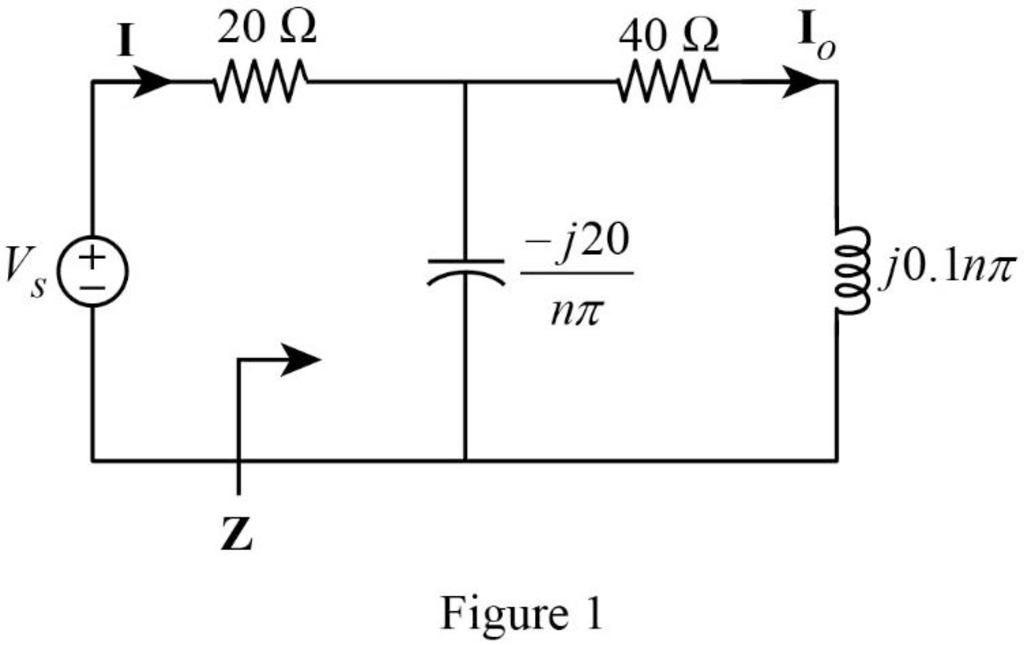
In Figure 1, the impedance is,
Simplify the above equation as follows,
The impedance
Substitute
The current
Substitute
The current
Substitute
Simplify the equation as follows,
The magnitude and phase angle of the current
In the time domain,
Where,
The phase angle
And,
The current
Conclusion:
Thus, the current through the inductor
Want to see more full solutions like this?
Chapter 17 Solutions
EBK FUNDAMENTALS OF ELECTRIC CIRCUITS


- Q1/Sketch the root locus for the system shown in Figure 1 and find the following: a. The exact point and gain where the locus crosses the jo-axis b. The breakaway point on the real axis c. The range of K within which the system is stable d. Angles of departure and arrival R(s) + K(s²-4s +20) C(s) (s+2)(s + 4)arrow_forwardExam2 Subject: (Numerical Analysis) Class: Third Date: 27/4/2025 Time: 60 minutes Q1. For what values of k does this system of equations has no solution? (use Gauss-Jordan eliminations) kx + y + z = 1 x+ky + z = 1 x+y+kz=1arrow_forwardConsider the Difference equation of a causal Linear time-invariant (LTI) system given by: (y(n) - 1.5y(n - 1) + 0.5y(n = 2) = x(n) a) Implement the difference equation model of this system. b) Find the system transfer function H(z). c) For an input x(n) = 8(n), determine the output response y(n). d) Verify the initial value theorem y(0) with part (c).arrow_forward
- Q5B. Find the type of the controller in the following figures and use real values to find the transfer function of three of them[ Hint Pi,Pd and Lead,lag are found so put the controller with its corresponding compensator]. R₁ R₂ Rz HE C2 RA HE R₁ R2 RA とarrow_forwardQ1// Sketch the root locus for the unity feedback system. Where G(s)=)= K S3+252 +25 and find the following a. Sketch the asymptotes b. The exact point and gain where the locus crosses the jo-axis c. The breakaway point on the real axis d. The range of K within which the system is stable e. Angles of departure and arrival.arrow_forwardDetermine X(w) for the given function shown in Figure (1) by applying the differentiation property of the Fourier Transform. Figure (1) -1 x(t)arrow_forward
- Can you solve a question with a drawing Determine X(w) for the given function shown in Figure (1) by applying the differentiation property of the Fourier Transform. Figure (1) -1 x(t)arrow_forwardAn inductor has a current flow of 3 A when connected to a 240 V, 60 Hz power line. The inductor has a wire resistance of 15 Find the Q of the inductorarrow_forwardصورة من s94850121arrow_forward
- The joint density function of two continuous random variables X and Yis: p(x, y) = {Keós (x + y) Find (i) the constant K 0 2 0arrow_forwardShow all the steps please, Solve for the current through R2 if E2 is replaced by a current source of 10mA using superposition theorem. R5=470Ω R2=1000Ω R6=820Ωarrow_forwardPlease solve it by explaining the steps. I am trying to prepare for my exam tomorrow, so any tips and tricks to solve similar problems are highly appreciated. Plus, this is a past exam I am using to prepare.arrow_forwardarrow_back_iosSEE MORE QUESTIONSarrow_forward_ios
 Introductory Circuit Analysis (13th Edition)Electrical EngineeringISBN:9780133923605Author:Robert L. BoylestadPublisher:PEARSON
 Delmar's Standard Textbook Of ElectricityElectrical EngineeringISBN:9781337900348Author:Stephen L. HermanPublisher:Cengage Learning
 Programmable Logic ControllersElectrical EngineeringISBN:9780073373843Author:Frank D. PetruzellaPublisher:McGraw-Hill Education
 Fundamentals of Electric CircuitsElectrical EngineeringISBN:9780078028229Author:Charles K Alexander, Matthew SadikuPublisher:McGraw-Hill Education
 Electric Circuits. (11th Edition)Electrical EngineeringISBN:9780134746968Author:James W. Nilsson, Susan RiedelPublisher:PEARSON
 Engineering ElectromagneticsElectrical EngineeringISBN:9780078028151Author:Hayt, William H. (william Hart), Jr, BUCK, John A.Publisher:Mcgraw-hill Education,