
Introductory Circuit Analysis; Laboratory Manual For Introductory Circuit Analysis Format: Kit/package/shrinkwrap
13th Edition
ISBN: 9780134297446
Author: Boylestad, Robert L.
Publisher: Prentice Hall
expand_more
expand_more
format_list_bulleted
Concept explainers
Videos
Textbook Question
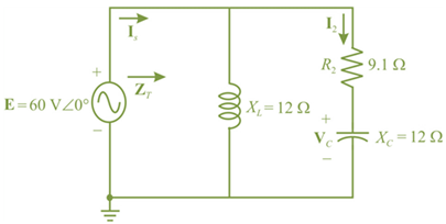
Chapter 17, Problem 3P
For the network in FIg. 17.40:
a. Find the total impedance ZT.
b. Find the current IS.
c. Calculate I2 using the current divider rule.
d. Calculate VC using the voltage divider rule.
e. Calculate the average power delivered to the network.
Expert Solution & Answer
Want to see the full answer?
Check out a sample textbook solution
Students have asked these similar questions
I need help with this problem and an explanation of the solution for the image described below. (Introduction to Signals and Systems)
I need help with this problem and an explanation of the solution for the image described below. (Introduction to Signals and Systems)
The input signal in the op-amp circuit of Fig. P7.80 is given by uin(t) =V0 coswt. Assuming the op amp is operating within its linear range, obtain an expression for your(t) by applying the phasor-domain technique and then evaluate it for wRC = 1.
Chapter 17 Solutions
Introductory Circuit Analysis; Laboratory Manual For Introductory Circuit Analysis Format: Kit/package/shrinkwrap
Ch. 17 - For theseries-parallel network in Fig.17.38. a....Ch. 17 - For the network in Fig. 17.39: a. Find the total...Ch. 17 - For the network in FIg. 17.40: a. Find the total...Ch. 17 - For the network in Fig. 17.41: a. Find the total...Ch. 17 - For the network in Fig. 17.42: a. Find the current...Ch. 17 - For the network in Fig. 17.43: a. Find the current...Ch. 17 - For the network in Fig. 17.44: a. Find the current...Ch. 17 - For the network in Fig. 17.45: a. Find the source...Ch. 17 - For the network of Fig. 17.46: a. Find the voltage...Ch. 17 - For the network in Fig. 17.47: a. Find the total...
Ch. 17 - For the network in Fig. 17.48: a. Find the total...Ch. 17 - For the network of Fig. 17.49: a. Find the total...Ch. 17 - For the network of Fig. 17.50: a. Find the total...Ch. 17 - Find the current I5 for the network in Fig. 17.51....Ch. 17 - Find the average power delivered to R5 in Fig....Ch. 17 - For the ladder network of Fig. 17.53: a. Find the...Ch. 17 - Prob. 17PCh. 17 - PSpice or Multisim For Problems 15 through 18, use...Ch. 17 - PSpice or Multisim For Problems 15 through 18, use...Ch. 17 - PSpice or Multisim For Problems 15 through 18, use...Ch. 17 - PSpice or Multisim For Problems 15 through 18, use...
Additional Engineering Textbook Solutions
Find more solutions based on key concepts
CONCEPT QUESTIONS
15.CQ3 The ball rolls without slipping on the fixed surface as shown. What is the direction ...
Vector Mechanics for Engineers: Statics and Dynamics
What types of coolant are used in vehicles?
Automotive Technology: Principles, Diagnosis, And Service (6th Edition) (halderman Automotive Series)
The ____________ is always transparent.
Web Development and Design Foundations with HTML5 (8th Edition)
Consider the adage Never ask a question for which you do not want the answer. a. Is following that adage ethica...
Experiencing MIS
How is the hydrodynamic entry length defined for flow in a pipe? Is the entry length longer in laminar or turbu...
Fluid Mechanics: Fundamentals and Applications
Knowledge Booster


Learn more about
Need a deep-dive on the concept behind this application? Look no further. Learn more about this topic, electrical-engineering and related others by exploring similar questions and additional content below.Similar questions
- For ui(t)=V0 coswt, obtain an expression for uout(t) in thecircuit of Fig. P7.82 and then evaluate it for V0 = 4 V, w = 400rad/s, R = 5 kW, and C = 2.5 μF.arrow_forwardCan you help me to solve the question?arrow_forwardThe input signal in the op-amp circuit of Fig. P7.81 is givenbyuin(t) = 0.5cos2000t V.Obtain an expression for uout(t) and then evaluate it forR1 = 2 kW, R2 = 10 kW, and C = 0.1 μF.arrow_forward
arrow_back_ios
SEE MORE QUESTIONS
arrow_forward_ios
Recommended textbooks for you
 Introductory Circuit Analysis (13th Edition)Electrical EngineeringISBN:9780133923605Author:Robert L. BoylestadPublisher:PEARSON
 Delmar's Standard Textbook Of ElectricityElectrical EngineeringISBN:9781337900348Author:Stephen L. HermanPublisher:Cengage Learning
 Programmable Logic ControllersElectrical EngineeringISBN:9780073373843Author:Frank D. PetruzellaPublisher:McGraw-Hill Education
 Fundamentals of Electric CircuitsElectrical EngineeringISBN:9780078028229Author:Charles K Alexander, Matthew SadikuPublisher:McGraw-Hill Education
 Electric Circuits. (11th Edition)Electrical EngineeringISBN:9780134746968Author:James W. Nilsson, Susan RiedelPublisher:PEARSON
 Engineering ElectromagneticsElectrical EngineeringISBN:9780078028151Author:Hayt, William H. (william Hart), Jr, BUCK, John A.Publisher:Mcgraw-hill Education,
Introductory Circuit Analysis (13th Edition)
Electrical Engineering
ISBN:9780133923605
Author:Robert L. Boylestad
Publisher:PEARSON
Delmar's Standard Textbook Of Electricity
Electrical Engineering
ISBN:9781337900348
Author:Stephen L. Herman
Publisher:Cengage Learning
Programmable Logic Controllers
Electrical Engineering
ISBN:9780073373843
Author:Frank D. Petruzella
Publisher:McGraw-Hill Education
Fundamentals of Electric Circuits
Electrical Engineering
ISBN:9780078028229
Author:Charles K Alexander, Matthew Sadiku
Publisher:McGraw-Hill Education
Electric Circuits. (11th Edition)
Electrical Engineering
ISBN:9780134746968
Author:James W. Nilsson, Susan Riedel
Publisher:PEARSON
Engineering Electromagnetics
Electrical Engineering
ISBN:9780078028151
Author:Hayt, William H. (william Hart), Jr, BUCK, John A.
Publisher:Mcgraw-hill Education,
Nodal Analysis for Circuits Explained; Author: Engineer4Free;https://www.youtube.com/watch?v=f-sbANgw4fo;License: Standard Youtube License