
Introductory Circuit Analysis; Laboratory Manual For Introductory Circuit Analysis Format: Kit/package/shrinkwrap
13th Edition
ISBN: 9780134297446
Author: Boylestad, Robert L.
Publisher: Prentice Hall
expand_more
expand_more
format_list_bulleted
Videos
Textbook Question
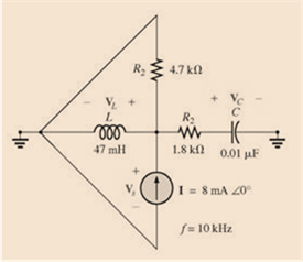
Chapter 17, Problem 9P
For the network of Fig. 17.46:
a. Find the voltage across the source current VS.
b. Find the voltage across the capacitor.
c. Find the voltag across the inductor.
Expert Solution & Answer
Want to see the full answer?
Check out a sample textbook solution
Students have asked these similar questions
Do part a,b,c and e
9.69 Find the equivalent admittance Yea of the circuit in
Fig. 9.76.
2S
1 S
-j3 S
-j2 S
www
ww
m
m
j5 S
j1 S
www
4 S
9.60 Obtain Zin for the circuit in Fig. 9.67.
Zin
25 Ω
www
Figure 9.67
For Prob. 9.60.
j152
m
-j500
20 Ω
61
Find
in the
of Fia 0.68
m
30 Ω
j102
Chapter 17 Solutions
Introductory Circuit Analysis; Laboratory Manual For Introductory Circuit Analysis Format: Kit/package/shrinkwrap
Ch. 17 - For theseries-parallel network in Fig.17.38. a....Ch. 17 - For the network in Fig. 17.39: a. Find the total...Ch. 17 - For the network in FIg. 17.40: a. Find the total...Ch. 17 - For the network in Fig. 17.41: a. Find the total...Ch. 17 - For the network in Fig. 17.42: a. Find the current...Ch. 17 - For the network in Fig. 17.43: a. Find the current...Ch. 17 - For the network in Fig. 17.44: a. Find the current...Ch. 17 - For the network in Fig. 17.45: a. Find the source...Ch. 17 - For the network of Fig. 17.46: a. Find the voltage...Ch. 17 - For the network in Fig. 17.47: a. Find the total...
Ch. 17 - For the network in Fig. 17.48: a. Find the total...Ch. 17 - For the network of Fig. 17.49: a. Find the total...Ch. 17 - For the network of Fig. 17.50: a. Find the total...Ch. 17 - Find the current I5 for the network in Fig. 17.51....Ch. 17 - Find the average power delivered to R5 in Fig....Ch. 17 - For the ladder network of Fig. 17.53: a. Find the...Ch. 17 - Prob. 17PCh. 17 - PSpice or Multisim For Problems 15 through 18, use...Ch. 17 - PSpice or Multisim For Problems 15 through 18, use...Ch. 17 - PSpice or Multisim For Problems 15 through 18, use...Ch. 17 - PSpice or Multisim For Problems 15 through 18, use...
Knowledge Booster


Learn more about
Need a deep-dive on the concept behind this application? Look no further. Learn more about this topic, electrical-engineering and related others by exploring similar questions and additional content below.Similar questions
- Figure 9.58 For Prob. 9.51. 9.52 If V. =8/30° V in the circuit of Fig. 9.59, find I¸. Is 4 10 Ω Figure 9.59 For Prob. 9.52. www -j5Q 5 Ω ww j5Q Voarrow_forward9.64 Find ZT and I in the circuit in Fig. 9.71. 30/90° V 492 www 602 www N ZT (+) Figure 9.71 For Prob. 9.64. -j10 18 Ωarrow_forward(b) 10 i dt + +6i(t) = 5 cos(5t + 22°) A dt 9.26 The loop equation for a series RLC circuit gives di+2i+ [ i dt = cos 21 A Assuming that the value of the integral at t=-00 is zero, find i(t) using the phasor method. 50 Figure 9arrow_forward
- EXAMPLE 3.11 Classify the following systems into LTI and non-LTI systems: a) y(t)=x(t)cos(t), b) y(t) = (x(t+1)+x(t) +x(t − 1))/3, and c) y(t) = cos(x(t)).arrow_forward9.42 Calculate vo(t) in the circuit of Fig. 9.49. 50 Ω 60 sin 200t V Figure 9.49 For Prob. 9.42. + 30 Ω www 50 μF + 0.1 H vo(t)arrow_forwardConsider the circuit shown in the figure. The current through the 6.00Ω resistor is 4.00 A, in the direction shown. Determine the value of(a) the overall voltage in the voltage source and (b) the current andvoltage for each resistor.arrow_forward
- Design a circuit to interface 8KB RAM to the 8085 microprocessor starting at address from 2000H.arrow_forwardHANDWRITTEN SOLUTION NOT USE CHATGPT Use the mesh - current method to find io in the circuit in ( Figure 1 ) . Suppose that v = 100V . Express your answer to three significant figures and include the appropriate units.arrow_forwardThe memory map of a 8 kB memory chip begins at the location E000H. The last location of the memory address.arrow_forward
- The question was to obtain the Fourier series for the periodic function f(x)= -2 when -πarrow_forwardConsider the homogeneous RLC circuit (no voltage source) shown in the diagram below. Before the switch is closed, the capacitor has an initial charge go and the circuit has an initial current go. R w i(t) q(t) C н After the switches closes, current flows through the circuit and the capacitor begins to discharge. The equation that describes the total voltage in the loop comes from Kirchoff's voltage law: di(t) L + Ri(t) + (t) = 0, dt (1) where i(t) and q(t) are the current and capacitor charge as a function of time, L is the inductance, R is the resistance, and C is the capacitance. Using the fact that the current equals the rate of change of the capacitor charge, and dividing by L, we can write the following homogeneous (no input source) differential equation for the charge on the capacitor: ä(t)+2ag(t)+wg(t) = 0, (2) where R a 2L and w₁ = C LC The solution to this second order linear differential equation can be written as: where 81= q(t) = Ae³¹- Bel 82 = (3) (4) (5)arrow_forward2. 1. A. Simplify the models in the following block diagrams to open loop models (Y/R = G). U(s) o G₁ ROS G₂ 1-GG G4 X₁ Σ az 51- 515 G6 G₂ 5 G₂ M b₁ b₂ Σ o Y(s) X₁ byarrow_forward
arrow_back_ios
SEE MORE QUESTIONS
arrow_forward_ios
Recommended textbooks for you
 Delmar's Standard Textbook Of ElectricityElectrical EngineeringISBN:9781337900348Author:Stephen L. HermanPublisher:Cengage Learning
Delmar's Standard Textbook Of Electricity
Electrical Engineering
ISBN:9781337900348
Author:Stephen L. Herman
Publisher:Cengage Learning
Resonance Circuits: LC Inductor-Capacitor Resonating Circuits; Author: Physics Videos by Eugene Khutoryansky;https://www.youtube.com/watch?v=Mq-PF1vo9QA;License: Standard YouTube License, CC-BY