
Introductory Circuit Analysis; Laboratory Manual For Introductory Circuit Analysis Format: Kit/package/shrinkwrap
13th Edition
ISBN: 9780134297446
Author: Boylestad, Robert L.
Publisher: Prentice Hall
expand_more
expand_more
format_list_bulleted
Concept explainers
Videos
Textbook Question
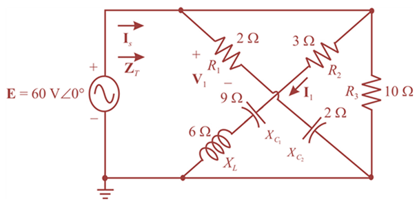
Chapter 17, Problem 13P
For the network of Fig. 17.50:
a. Find the total impedance ZT.
b. Find the voltage V1 across the 3
c. Find the current I1 using Ohm’s law.
d. Find the current Is.
Expert Solution & Answer
Want to see the full answer?
Check out a sample textbook solution
Students have asked these similar questions
a diode current is 0.6 ma when applied voltage is 400 mv and 20 ma when applied voltage is 500 mv.find n.assume vt=26mv
4. Impedance of each leg of the load is 2+j2 ohms. Find the 3-phase power consumed by the loads.
I need help with this problem and an explanation of the solution for the image described below. (Introduction to Signals and Systems)
Chapter 17 Solutions
Introductory Circuit Analysis; Laboratory Manual For Introductory Circuit Analysis Format: Kit/package/shrinkwrap
Ch. 17 - For theseries-parallel network in Fig.17.38. a....Ch. 17 - For the network in Fig. 17.39: a. Find the total...Ch. 17 - For the network in FIg. 17.40: a. Find the total...Ch. 17 - For the network in Fig. 17.41: a. Find the total...Ch. 17 - For the network in Fig. 17.42: a. Find the current...Ch. 17 - For the network in Fig. 17.43: a. Find the current...Ch. 17 - For the network in Fig. 17.44: a. Find the current...Ch. 17 - For the network in Fig. 17.45: a. Find the source...Ch. 17 - For the network of Fig. 17.46: a. Find the voltage...Ch. 17 - For the network in Fig. 17.47: a. Find the total...
Ch. 17 - For the network in Fig. 17.48: a. Find the total...Ch. 17 - For the network of Fig. 17.49: a. Find the total...Ch. 17 - For the network of Fig. 17.50: a. Find the total...Ch. 17 - Find the current I5 for the network in Fig. 17.51....Ch. 17 - Find the average power delivered to R5 in Fig....Ch. 17 - For the ladder network of Fig. 17.53: a. Find the...Ch. 17 - Prob. 17PCh. 17 - PSpice or Multisim For Problems 15 through 18, use...Ch. 17 - PSpice or Multisim For Problems 15 through 18, use...Ch. 17 - PSpice or Multisim For Problems 15 through 18, use...Ch. 17 - PSpice or Multisim For Problems 15 through 18, use...
Additional Engineering Textbook Solutions
Find more solutions based on key concepts
Assume a telephone signal travels through a cable at two-thirds the speed of light. How long does it take the s...
Electric Circuits. (11th Edition)
17–1C A high-speed aircraft is cruising in still air. How does the temperature of air at the nose of the aircra...
Thermodynamics: An Engineering Approach
This optional Google account security feature sends you a message with a code that you must enter, in addition ...
SURVEY OF OPERATING SYSTEMS
CONCEPT QUESTIONS
15.CQ3 The ball rolls without slipping on the fixed surface as shown. What is the direction ...
Vector Mechanics for Engineers: Statics and Dynamics
A nozzle at A discharges water with an initial velocity of 36 ft/s at an angle with the horizontal. Determine ...
Vector Mechanics For Engineers
How are relationships between tables expressed in a relational database?
Modern Database Management
Knowledge Booster


Learn more about
Need a deep-dive on the concept behind this application? Look no further. Learn more about this topic, electrical-engineering and related others by exploring similar questions and additional content below.Similar questions
- Using C-H Theorem to find A2, A3 for A=( 6 6arrow_forward- Apply the Gauss-Jordan method to the following system: X1 X2 X3+ x4 = 1 X1+2x2+2x3 + 2x4 = 0 X1+2x2+3x3 + 3x4 = 0 X1+2x2+3x3 + 4x4 = 0arrow_forwardSolve the following circuit using Gauss Elimination method, V/R=1; R R R R 1 R 12 13 V Varrow_forward
- NEED HANDWRITTEN SOLUTION DO NOT USE AIarrow_forwardI need help with this problem and an explanation of the solution for the image described below. (Introduction to Signals and Systems)arrow_forwardI need help with this problem and an explanation of the solution for the image described below. (Introduction to Signals and Systems)arrow_forward
arrow_back_ios
SEE MORE QUESTIONS
arrow_forward_ios
Recommended textbooks for you
 Introductory Circuit Analysis (13th Edition)Electrical EngineeringISBN:9780133923605Author:Robert L. BoylestadPublisher:PEARSON
 Delmar's Standard Textbook Of ElectricityElectrical EngineeringISBN:9781337900348Author:Stephen L. HermanPublisher:Cengage Learning
 Programmable Logic ControllersElectrical EngineeringISBN:9780073373843Author:Frank D. PetruzellaPublisher:McGraw-Hill Education
 Fundamentals of Electric CircuitsElectrical EngineeringISBN:9780078028229Author:Charles K Alexander, Matthew SadikuPublisher:McGraw-Hill Education
 Electric Circuits. (11th Edition)Electrical EngineeringISBN:9780134746968Author:James W. Nilsson, Susan RiedelPublisher:PEARSON
 Engineering ElectromagneticsElectrical EngineeringISBN:9780078028151Author:Hayt, William H. (william Hart), Jr, BUCK, John A.Publisher:Mcgraw-hill Education,
Introductory Circuit Analysis (13th Edition)
Electrical Engineering
ISBN:9780133923605
Author:Robert L. Boylestad
Publisher:PEARSON
Delmar's Standard Textbook Of Electricity
Electrical Engineering
ISBN:9781337900348
Author:Stephen L. Herman
Publisher:Cengage Learning
Programmable Logic Controllers
Electrical Engineering
ISBN:9780073373843
Author:Frank D. Petruzella
Publisher:McGraw-Hill Education
Fundamentals of Electric Circuits
Electrical Engineering
ISBN:9780078028229
Author:Charles K Alexander, Matthew Sadiku
Publisher:McGraw-Hill Education
Electric Circuits. (11th Edition)
Electrical Engineering
ISBN:9780134746968
Author:James W. Nilsson, Susan Riedel
Publisher:PEARSON
Engineering Electromagnetics
Electrical Engineering
ISBN:9780078028151
Author:Hayt, William H. (william Hart), Jr, BUCK, John A.
Publisher:Mcgraw-hill Education,
Nodal Analysis for Circuits Explained; Author: Engineer4Free;https://www.youtube.com/watch?v=f-sbANgw4fo;License: Standard Youtube License