
EE 98: Fundamentals of Electrical Circuits - With Connect Access
6th Edition
ISBN: 9781259981807
Author: Alexander
Publisher: MCG
expand_more
expand_more
format_list_bulleted
Concept explainers
Videos
Textbook Question
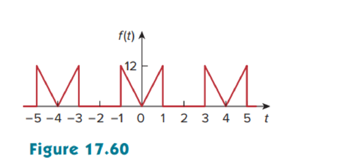
Chapter 17, Problem 22P
Calculate the Fourier coefficients for the function in Fig. 17.60.
Expert Solution & Answer
Want to see the full answer?
Check out a sample textbook solution
Students have asked these similar questions
For the circuit shown, find
(i) closed-loop voltage gain
(ii) Z i of the circuit
(iii) f_max. The slew rate is 0.6V/us.
((write your answer in Kilo ohm))
2Vpp
R
ww
20 kQ
R₁
ww
200 ΚΩ
9+18 V
- 18 V
10 kn R₁₂
ΚΩ
((write your answer in KHz))
illustrate the phenomenon of phase reversal in CE amplifier
i- When signal current =OA, so IB-8uA
ii- When input signal reaches positive peak, so IB=16uA
ii- When input signal reaches negative peak, so IB=4uA
R₁
www
+ Vcc = 12V
Rc=6kn
16 A
8 μA
4 μА
0
www
RE
ẞ = 100
VC
In the circuit shown, find the voltage gain. Given that ẞ = 80 and input resistance Rin=2kQ.
SIGNAL
+10 V
Rc=6kn
4-2
210
Chapter 17 Solutions
EE 98: Fundamentals of Electrical Circuits - With Connect Access
Ch. 17.2 - Find the Fourier series of the square wave in Fig....Ch. 17.2 - Determine the Fourier series of the sawtooth...Ch. 17.3 - Prob. 3PPCh. 17.3 - Find the Fourier series expansion of the function...Ch. 17.3 - Prob. 5PPCh. 17.4 - Prob. 6PPCh. 17.4 - If the input voltage in the circuit of Fig. 17.24...Ch. 17.5 - The voltage and current at the terminals of a...Ch. 17.5 - Find the rms value of the periodic current i(t) =...Ch. 17.6 - Obtain the complex Fourier series of the function...
Ch. 17.6 - Obtain the complex Fourier series expansion of...Ch. 17.7 - Prob. 12PPCh. 17.8 - Rework Example 17.14 if the low-pass filter is...Ch. 17 - Which of the following cannot be a Fourier series?...Ch. 17 - If ft=t,0t,ft+n=ft, the value of 0 is (a) 1 (b) 2...Ch. 17 - Which of the following are even functions? (a) t +...Ch. 17 - Prob. 4RQCh. 17 - Prob. 5RQCh. 17 - If f(t) = 10 + 8 cos t + 4 cos 3t + 2 cos 5t + ,...Ch. 17 - Prob. 7RQCh. 17 - The plot of |cn| versus n0 is called: (a) complex...Ch. 17 - Prob. 9RQCh. 17 - Prob. 10RQCh. 17 - Evaluate each of the following functions and see...Ch. 17 - Using MATLAB, synthesize the periodic waveform for...Ch. 17 - Given that Fourier coefficients a0, an, and bn of...Ch. 17 - Find the Fourier series expansion of the backward...Ch. 17 - Prob. 5PCh. 17 - Find the trigonometric Fourier series for f t =...Ch. 17 - Determine the Fourier series of the periodic...Ch. 17 - Using Fig. 17.51, design a problem to help other...Ch. 17 - Determine the Fourier coefficients an and bn of...Ch. 17 - Find the exponential Fourier series for the...Ch. 17 - Obtain the exponential Fourier series for the...Ch. 17 - Prob. 12PCh. 17 - Prob. 13PCh. 17 - Find the quadrature (cosine and sine) form of the...Ch. 17 - Express the Fourier series...Ch. 17 - The waveform in Fig. 17.55(a) has the following...Ch. 17 - Prob. 17PCh. 17 - Prob. 18PCh. 17 - Obtain the Fourier series for the periodic...Ch. 17 - Prob. 20PCh. 17 - Prob. 21PCh. 17 - Calculate the Fourier coefficients for the...Ch. 17 - Using Fig. 17.61, design a problem to help other...Ch. 17 - Prob. 24PCh. 17 - Determine the Fourier series representation of the...Ch. 17 - Find the Fourier series representation of the...Ch. 17 - For the waveform shown in Fig. 17.65 below, (a)...Ch. 17 - Obtain the trigonometric Fourier series for the...Ch. 17 - Prob. 29PCh. 17 - Prob. 30PCh. 17 - Prob. 31PCh. 17 - Prob. 32PCh. 17 - Prob. 33PCh. 17 - Prob. 34PCh. 17 - Prob. 35PCh. 17 - Prob. 36PCh. 17 - If the periodic current waveform in Fig. 17.73(a)...Ch. 17 - Prob. 38PCh. 17 - Prob. 39PCh. 17 - The full-wave rectified sinusoidal voltage in Fig....Ch. 17 - Prob. 42PCh. 17 - The voltage across the terminals of a circuit is...Ch. 17 - Prob. 44PCh. 17 - A series RLC circuit has R = 10 , L = 2 mH, and C...Ch. 17 - Prob. 46PCh. 17 - Prob. 47PCh. 17 - Prob. 48PCh. 17 - Prob. 49PCh. 17 - Prob. 50PCh. 17 - Prob. 51PCh. 17 - Prob. 52PCh. 17 - Prob. 53PCh. 17 - Find the exponential Fourier series for the...Ch. 17 - Obtain the exponential Fourier series expansion of...Ch. 17 - The Fourier series trigonometric representation of...Ch. 17 - Prob. 57PCh. 17 - Find the exponential Fourier series of a function...Ch. 17 - Prob. 59PCh. 17 - Obtain the complex Fourier coefficients of the...Ch. 17 - The spectra of the Fourier series of a function...Ch. 17 - Prob. 62PCh. 17 - Plot the amplitude spectrum for the signal f2(t)...Ch. 17 - Prob. 64PCh. 17 - Prob. 65PCh. 17 - Prob. 66PCh. 17 - Prob. 67PCh. 17 - Prob. 68PCh. 17 - Prob. 69PCh. 17 - Design a problem to help other students better...Ch. 17 - Prob. 71PCh. 17 - Prob. 72PCh. 17 - Prob. 73PCh. 17 - Prob. 74PCh. 17 - Prob. 75PCh. 17 - Prob. 76PCh. 17 - Prob. 77CPCh. 17 - Prob. 78CPCh. 17 - Consider the full-wave rectified sinusoidal...Ch. 17 - Prob. 82CP
Knowledge Booster


Learn more about
Need a deep-dive on the concept behind this application? Look no further. Learn more about this topic, electrical-engineering and related others by exploring similar questions and additional content below.Similar questions
- For the transistor amplifier shown, R₁-11kQ, R2=6kQ, Rc=2kQ, RE-3kQ and R₁=2k0. (i) Draw d.c. load line (ii) Determine the DC operating point (iii) Draw a.c. load line. Assume V_BE = 0.7 V. and determine the new operating point + Vcc = 15 V RC Cc Cin R1 wwwwww wwwww R₁₂ RE CE RLarrow_forwardthe first part is the second part write your answer such as: (AND, OR, INVERTER, NAND, NOR) D₁ AK D, R₁ B K First Part? the third part is , and the total are R4 R7 Output R5 R₁ T R6 R3 -UBB Second Part? Third Part? Total?arrow_forwardA multistage amplifier has six stages each of which has a power gain of 40. what is the - Total gain of the amplifier in db ? ii- If the negative feedback of 15db is employed, find the resultant gainarrow_forward
- 9.36 Consider the finite-state machine logic implementation in Figure P9.36. (a) Determine the next-state and output logic expressions. (b) Determine the number of possible states. J1 Clk K₁ 101 Ут J2 Clk K₂ Clk Figure P9.36 0 y2 10arrow_forward9.34 Consider the finite-state machine logic implementation in Figure P9.34. (a) Determine the next-state and output logic expressions. (b) Determine the number of possible states. (c) Construct a state assigned table. (d) Construct a state table. (e) Construct a state diagram. (f) Determine the function of the finite-state machine. T₁ x Clk Figure P9.34 Q Clk Q الا T₂ Q 32 Clk Q T3 Q Clk Q Узarrow_forward9.35 Consider the finite-state machine logic implementation in Figure P9.35. (a) Determine the next-state and output logic expressions. (b) Determine the number of possible states. (c) Construct a state assigned table. (d) Construct a state table. (e) Construct a state diagram. (f) Determine the function of the finite-state machine. Clk J Clk K₁ 10 Ут J2 Clk K₂ 10 32 Figure P9.35arrow_forward
- 9.56 Using JK flip-flops, design a synchronous counter that counts in the sequence 1, 3, 0, 2, 1, ... The counter counts only when its enable input x is equal to 1; otherwise, the counter is idle.arrow_forward9.65 Using T flip-flops, design a synchronous counter that counts in the sequence 0, 2, 4, 6, 0, ... The counter counts only when its enable input x is equal to 1; otherwise, the counter is idle.arrow_forward2 Using D flip-flops, design a synchronous counter that counts in the sequence 1, 4, 7, 1, The counter counts only when its enable input x is equal to 1; otherwise, the counter is idle.arrow_forward
- Q1: Write a VHDL code to implement the finite state machine described in the state diagram shown below. Clk D 0 CIK Q D 0 Cik Q =arrow_forwardQ1: Consider the finite state machine logic implementation in Fig. shown below: Construct the state diagram. Repeat the circuit design using j-k flip flop. r" Clk Y D' Y, Clk Q D Clk 10 0 22 3'2arrow_forwardQ: Write a VHDL code to implement the finite state machine described in the state diagram shown below. T 2 Clk Q Clk T₂ 0 la Clk T3 Q Cik 0arrow_forward
arrow_back_ios
SEE MORE QUESTIONS
arrow_forward_ios
Recommended textbooks for you
 Introductory Circuit Analysis (13th Edition)Electrical EngineeringISBN:9780133923605Author:Robert L. BoylestadPublisher:PEARSON
 Delmar's Standard Textbook Of ElectricityElectrical EngineeringISBN:9781337900348Author:Stephen L. HermanPublisher:Cengage Learning
 Programmable Logic ControllersElectrical EngineeringISBN:9780073373843Author:Frank D. PetruzellaPublisher:McGraw-Hill Education
 Fundamentals of Electric CircuitsElectrical EngineeringISBN:9780078028229Author:Charles K Alexander, Matthew SadikuPublisher:McGraw-Hill Education
 Electric Circuits. (11th Edition)Electrical EngineeringISBN:9780134746968Author:James W. Nilsson, Susan RiedelPublisher:PEARSON
 Engineering ElectromagneticsElectrical EngineeringISBN:9780078028151Author:Hayt, William H. (william Hart), Jr, BUCK, John A.Publisher:Mcgraw-hill Education,
Introductory Circuit Analysis (13th Edition)
Electrical Engineering
ISBN:9780133923605
Author:Robert L. Boylestad
Publisher:PEARSON
Delmar's Standard Textbook Of Electricity
Electrical Engineering
ISBN:9781337900348
Author:Stephen L. Herman
Publisher:Cengage Learning
Programmable Logic Controllers
Electrical Engineering
ISBN:9780073373843
Author:Frank D. Petruzella
Publisher:McGraw-Hill Education
Fundamentals of Electric Circuits
Electrical Engineering
ISBN:9780078028229
Author:Charles K Alexander, Matthew Sadiku
Publisher:McGraw-Hill Education
Electric Circuits. (11th Edition)
Electrical Engineering
ISBN:9780134746968
Author:James W. Nilsson, Susan Riedel
Publisher:PEARSON
Engineering Electromagnetics
Electrical Engineering
ISBN:9780078028151
Author:Hayt, William H. (william Hart), Jr, BUCK, John A.
Publisher:Mcgraw-hill Education,
Intro to FOURIER SERIES: The Big Idea; Author: Dr. Trefor Bazett;https://www.youtube.com/watch?v=wmCIrpLBFds;License: Standard Youtube License