
Concept explainers
Find the Fourier series for the signal shown in Figure 17.58 and verify it using MATLAB and find the value of
Answer to Problem 20P
The Fourier series
Explanation of Solution
Given data:
Refer to Figure 17.58 in the textbook.
Formula used:
Write the expression to calculate the fundamental angular frequency.
Here,
Write the general expression to calculate trigonometric Fourier series of
Here,
Calculation:
The given waveform is drawn as Figure 1.
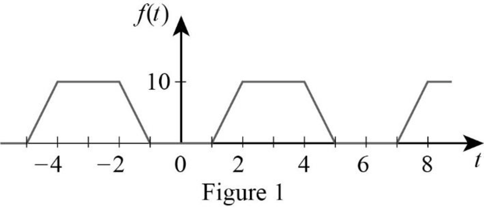
Refer to Figure 1, the waveform is symmetrical about the vertical axis. The signal
Write the expressions for Fourier coefficients for an even function.
Refer to the Figure 1. The Fourier series even function of the waveform is defined as,
The time period of the function in Figure 1 is,
Substitute
Substitute
Simplify the above equation to find
Substitute
Simplify the above equation to find
Simplify the above equation to find
Assume the following to reduce the equation (5).
Substitute the equations (6) in equation (5) to find
Consider the following integration formula.
Compare the equations (6) and (8) to simplify the equation (6).
Using the equation (8), the equation (6) can be reduced as,
Simplify the above equation to find
Substitute
Substitute
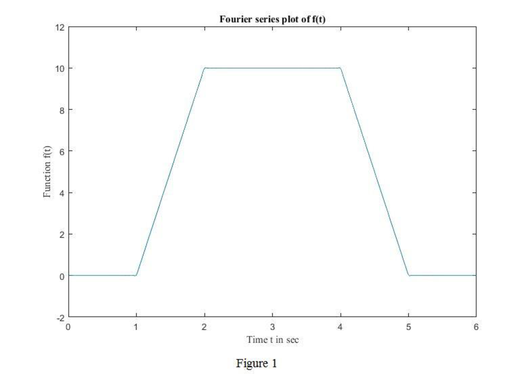
Following includes the MATLAB code to obtain the waveform in Figure 1 using the obtained function
MATLAB Code:
t=0:.01:6;
f=5*ones(size(t));
for n=1:1:99
f=f+(60/(n^2*pi^2))*(cos(2*pi*n/3)-cos(pi*n/3))*cos(n*pi*t/3);
end
plot(t,f)
title('Fourier series plot of f(t)');
xlabel('Time t in sec');
ylabel('Function f(t)');
Output:
The output of the MATLAB is the Fourier series plot of the function
Substitute
Simplify the above equation to find
Write the MATLAB code to find
MATLAB code:
t=2;
f=5*ones(size(t));
for n=1:1:5
f=f+(60/(n^2*pi^2))*(cos(2*pi*n/3)-cos(pi*n/3))*cos(n*pi*t/3);
end
disp(f)
The Output displays the value of
9.5122
This output is approximately satisfied with calculated value of
Conclusion:
Thus, the Fourier series
Want to see more full solutions like this?
Chapter 17 Solutions
EE 98: Fundamentals of Electrical Circuits - With Connect Access


- Q3arrow_forwardGiven the logic function F(A,B,C,D) = Σm(1,2,3,4,9,10,11,12) (i) Write the truth table of the logic function. (ii) Use the Karnaugh-map method to find the simplest sum-of-products (SOP) expression of function F. (iii) Implement the minimized function with NAND gates only. (iv) Show that the Boolean function F can be constructed using exclusive-OR gates (v) Express the same logic function in a product-of-sums (POS) form. (vi) Simplify your function in product-of-sums (POS). (vii) Use a decoder with external AND gates only to implement F in its product-of- sums (POS) form (assume AND gates with any number of inputs are available). Note: You can use NAND gates with any number of inputs you may need. Assume, as well, that the input variables are available in both true and complemented form.arrow_forwardProblem A medical research facility is developing a proton accelerator for cancer treatment using proton therapy. The accelerator is designed to generate a beam of protons that precisely targets and destroys cancerous cells while minimizing damage to surrounding healthy tissue. However, there is an issue with the beam trajectory, which deviates from the intended direction when subjected to electric and magnetic fields. A team of engineers has been assigned to diagnose and resolve this issue. -The accelerator generates a beam of 10" protons with an initial velocity of v = 3 × 10° m/s in the y-axis direction. -An electric field of E = 200 kV/m is applied in the negative z-axis using a set of electrodes. -A magnetic field of B = 0.1T is applied along the z-axis using a solenoid to redirect the protons. - However, the beam does not align with the expected trajectory, indicating an error in field configuration or an unaccounted force acting on the protons. Answer the following questions 1.…arrow_forward
- Design a synchronous binary up-counter using 4 negative edge-triggered JK flip-flops provided with a clock. The states (sequences) 1100, 1001 and 1000 are considered as unused states. (i) Draw the state diagram of the counter. (ii) Build the counter's state table showing the synchronous inputs of the JK flip- flops as well. (iii) Using Karnaugh-maps, find the minimal sum-of-products (SOP) form of the equations for the inputs to the flip-flops; assume the next states of the unused combinations to be "don't care states”. (iv) Draw the logic circuit of the counter.arrow_forwardDesign a synchronous sequential circuit with two T flip-flops A and B, one input y and one output Z. When y = 0, the state of the circuit remains the same and Z= 0. When y = 1, the circuit goes through the following state transitions from 00 to 01 to 11 to 10 and back to 00, then repeats, while Z = y for states 10 and 11 and Z = y for states 00 and 01. Assume that state 00 is in the initial state. Provide a table that shows: the input and output values the states (present and next) for the two T flip-flops (i) (a) (b) (ii) (iii) Draw the resulting logic circuit. Using Karnaugh-maps, find the minimal sum-of-products (SOP) form of the equations for the inputs to the T flip-flops and the output (Z).arrow_forwardDesign a modulo-5 ripple (asynchronous) down-counter with D flip-flops and draw the corresponding logic circuit. (i) Build the state diagram and extract the state table(ii)Draw the logic circuit(iii) What is the maximum modulus of the counter?arrow_forward
- Don't use ai to answer I will report you answerarrow_forward(i) The following two numbers are represented in unsigned binary: A= (10101)2 B= (10011)2 Represent these two numbers in signed 1's complement form and perform the following binary arithmetic operations using the 1's complement method. Use a total of 7 bits to represent both numbers and results including the sign bit. C = A + B; D=A-B.arrow_forwardDon't use ai to answer I will report you answerarrow_forward
 Introductory Circuit Analysis (13th Edition)Electrical EngineeringISBN:9780133923605Author:Robert L. BoylestadPublisher:PEARSON
 Delmar's Standard Textbook Of ElectricityElectrical EngineeringISBN:9781337900348Author:Stephen L. HermanPublisher:Cengage Learning
 Programmable Logic ControllersElectrical EngineeringISBN:9780073373843Author:Frank D. PetruzellaPublisher:McGraw-Hill Education
 Fundamentals of Electric CircuitsElectrical EngineeringISBN:9780078028229Author:Charles K Alexander, Matthew SadikuPublisher:McGraw-Hill Education
 Electric Circuits. (11th Edition)Electrical EngineeringISBN:9780134746968Author:James W. Nilsson, Susan RiedelPublisher:PEARSON
 Engineering ElectromagneticsElectrical EngineeringISBN:9780078028151Author:Hayt, William H. (william Hart), Jr, BUCK, John A.Publisher:Mcgraw-hill Education,